
Owner's manual


474 NT8D09 Analog Message Waiting Line card
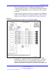
Table 199
Analog message waiting line card - backplane pinouts
Backplane
pinout*
Lead
designations
Backplane
pinout*
Lead
designations
12A Line 0, Ring 12B Line 0, Tip
13A Line 1, Ring 13B Line 1, Tip
14A Line 2, Ring 14B Line 2, Tip
15A Line 3, Ring 15B Line 3, Tip
16A Line 4, Ring 16B Line 4, Tip
17A Line 5, Ring 17B Line 5, Tip
18A Line 6, Ring 18B Line 6, Tip
19A Line 7, Ring 18B Line 7, Tip
62A Line 8, Ring 62B Line 8, Tip
63A Line 9, Ring 63B Line 9, Tip
64A Line 10, Ring 64B Line 10, Tip
65A Line 11, Ring 65B Line 11, Tip
66A Line 12, Ring 66B Line 12, Tip
67A Line 13, Ring 67B Line 13, Tip
68A Line 14, Ring 68B Line 14, Tip
69A Line 15, Ring 69B Line 15, Tip
* These pinouts apply to both NT8D37 and NT8D11 backplanes.
Configuration
This section outlines the procedures for configuring the switches
and jumpers on the NT8D09 Analog Message Waiting Line card and
configuring the system software to properly recognize the card. Figure 122
"Analog message waiting line card - jumper block and switch locations"
(page 477) shows where the switches and jumper blocks are located on
this board.
Jumper and switch settings
The NT8D09 Analog Message Waiting Line card has no user-configurable
jumpers or switches. The card derives its address from its position in the
backplane and reports that information back to the CPU through the LAN
Link interface.
Software service changes
Individual line interface units on the NT8D09 Analog Message Waiting
Line card are configured using the Analog (500/2500-type) Telephone
Administration program LD 10.
Nortel Communication Server 1000
Circuit Card Reference
NN43001-311 02.06 Standard
27 August 2008
Copyright © 2003-2008 Nortel Networks
.