
Owner's manual

Functional description 341
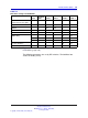
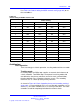
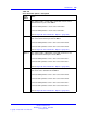
Table 137
DIP switch settings for NT5D97AD
Card
Trunks 0
and 1 Port 0 Port 1 Trunk 0 Trunk 1
ENB/DSB
mounted on the face plate
S1
Ring Ground S16
DPNSS S8 S9
MSDL S9
TX Mode S2 S10
S3 S13
S4 S14
LBO Setting
S5 S15
Receiver Interface S6 S11
General Purpose S12 S7
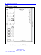
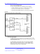
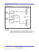
Refer to DIP switch locations in Figure 94 "Dip switches locations for
NT5D97AD" (page 342).
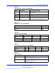
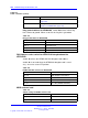
The following parameters are set by DIP switches. The boldface font
shows the factory set-up.
Nortel Communication Server 1000
Circuit Card Reference
NN43001-311 02.06 Standard
27 August 2008
Copyright © 2003-2008 Nortel Networks
.