
Owner's manual

270 NT5D33 and NT5D34 Lineside E1 Interface cards
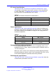
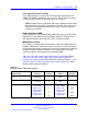
Table 101
LEI card - Switch 1 dip switch settings (cont’d.)
Characteristic Selection
Switch
Position
Switch
Setting
Factory
Default
Card type for ringer
allocation
XTI = 19
XMLC = 18
7
7
ON
OFF
OFF
E1 signaling See Table 102
"LEI card -
signaling-type dip
switch settings"
(page 270)
8
OFF OFF
When dip switch #1, positions 2 and 8 are set to "Table," AB Bits are
configured by the user through the Set Mode MMI command (see “Set
Mode” (page 294)). Otherwise, the signaling scheme selected by dip
switch 1, positions 2 and 8 are used.
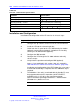
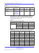
Table 102
LEI card - signaling-type dip switch settings
Switch #1
Characteristic Selection
Position 2 Position 8
Loop start OFF OFF
Ground start ON OFF
Australian P2 OFF ON
Signaling Type
Table ON ON
Table 103
LEI card - XPEC address dip switch settings (Switch S1, positions 3-6)
XPEC
Address
S1 Switch
Position 3
S1 Switch
Position 4
S1 Switch
Position 5
S1 Switch
Position 6
00
OFF OFF OFF OFF
01
ON OFF OFF OFF
02
OFF ON OFF OFF
03
ON ON OFF OFF
04
OFF OFF ON OFF
05
ON OFF ON OFF
06
OFF ON ON OFF
07
ON ON ON OFF
08
OFF OFF OFF ON
09
ON OFF OFF ON
10
OFF ON OFF ON
Nortel Communication Server 1000
Circuit Card Reference
NN43001-311 02.06 Standard
27 August 2008
Copyright © 2003-2008 Nortel Networks
.