
Owner's manual

Electrical specifications 265
E1 channel specifications
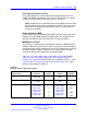
Table 98 "LEI card - line interface unit electrical characteristics" (page
265) provides specifications for the 30 E1 channels. Each characteristic
is set by a dip switch. “Installation and Configuration” (page 266) for a
discussion of the corresponding dip switch settings.
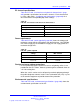
Table 98
LEI card - line interface unit electrical characteristics
Characteristics
Description
Framing CRC-4 or FAS, only
Coding AMI or HDB3
Signaling Loop or ground start A/B robbed-bit
Distance to LTU 0-199.6 meters (0-655 feet)
Power requirements
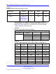
Table 99 "LEI card - power required" (page 265) shows the voltage and
maximum current that the LEI requires from the backplane. One NT8D06
IPE Power Supply AC or NT6D40 IPE Supply DC can supply power to a
maximum of eight LEIs.
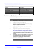
Table 99
LEI card - power required
Voltage
Max. Current
5.0 V dc 1.6 Amp
+15.0 V dc 150 mA
-15.0 V dc 150 mA
Foreign and surge voltage protections
In-circuit protection against power line crosses or lightning strikes is not
provided on the LEI. It does, however, protect against accidental shorts to
–52 V dc analog lines.
When the card is used to service off-premise terminal equipment through
the public telephone network, install a Line Termination Unit (LTU) as part
of the terminal equipment to provide external line protection.
Environmental specifications
Table 100 "LEI card - environmental specifications" (page 266) shows the
environmental specifications of the LEI.
Nortel Communication Server 1000
Circuit Card Reference
NN43001-311 02.06 Standard
27 August 2008
Copyright © 2003-2008 Nortel Networks
.