
Owner's manual


226 NT5D11 and NT5D14 Lineside T1 Interface cards
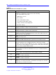
Table 90
MMI commands and command sets (cont’d.)
Command
Description
AE
Alarm Enable
Enables all alarms
CA
Clear Alarm
Clears all alarms, terminates line processing, and resets the T1 bit error rate and
frame slip counters
CAL
Clear Alarm Log
Clears the alarm log
CE
Clear Error
Clears the error counter for the T1
D A [P] Display Alarms [Pause]
Displays the alarm log – a list of the most recent 100 alarms along with time and
date stamps
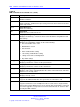
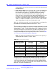
DC
Display Configuration
Displays the configuration settings for the cards including:
• the serial number of the card
• MMI firmware version
•
date and time
•
alarm enable/disable setting
• self-clearing enable/disable setting
• settings entered in Set Configuration
• dip switch settings
D H [P]
Display History [Pause]
Displays performance counters for the past 24 hours.
DP
Display Performance
Displays performance counters for the current hour.
D S [P]
Display Status [Pause]
Displays carrier status, including whether the card is in the alarm state, and what
alarm level is currently active.
H or ? Help
Displays the help screen
L Login
Logs into the MMI terminal when the system has one Lineside T1 card
Q
Quit
Logs the terminal user out. If multiple Lineside T1 cards share a single terminal,
logout after using the MMI. Because of the shared daisy-chained link, if a Lineside
T1 card is logged in, it occupies the bus and no other Lineside T1 cards are able
to notify the MMI of alarms.
Nortel Communication Server 1000
Circuit Card Reference
NN43001-311 02.06 Standard
27 August 2008
Copyright © 2003-2008 Nortel Networks
.