
Owner's manual


Front panel connector pin assignments 157
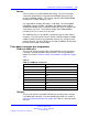
Table 61
Front panel LED functionality (cont’d.)
LED
Color
Functionality Default
LED3 Green CompactFlash activity -Off
LED4
Green CompactFlash activity -Off
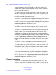
ITP connector (25 PIN, Debug Only)
Table 62
ITP connector pin outs
Pin
Signal Name
Pin
Signal Name
P1 GND P2 GND
P3 BPM0N P4 NC
P5
BPM1N
P6
RESETN
P7 BPM2N P8 GND
P9 BPM3N P10 TDI
P11
BPM4N
P12
TMS
P13 BPM5N P14 TRSTN
P15
ITP_CPURSTN
P16
TCK
P17
TCK
P18
NC
P19 CLK P20 GND
P21
CLKN
P22
PWR
P23 BPM5N P24 TDO
P25 GND
Post 80 Debug LEDs (Optional)
CP PIV has post 80 debug LEDs to assist in debugging the board and
solving boot related problems. Using a GPCS from Super I/O X-bus, data
lines are latched using latch 74F374. These help identify Post 80 codes.
This feature is available only in debug boards.
Nortel Communication Server 1000
Circuit Card Reference
NN43001-311 02.06 Standard
27 August 2008
Copyright © 2003-2008 Nortel Networks
.