
User's Manual

1 Copyright © 2017 Nortek Security & Control LLC
GC-GRILL1-B-345
GRILL GUARD
INSTALLATION INSTRUCTIONS
The GoControl® Grill Guard (device) is a contact ON/OFF sensor
that alerts your security panel (and op onally the smartphone
with Alarm.com) when the knob on a grill/stove is turned ON. It
is compa ble with 2GIG security panels, including GC2, GC3, and
Vario.
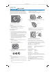
INNER MARKS
KNOB STEM
SLEEVE
MAGNET
GRILL
KNOB
DISC
Figure 1. Grill Knob Device Assembly
Contents
Verify that the package contains the following:
• One (1) Grill Guard disc - w/ pre-installed ba eries and
adhesive strips a ached
• Knob stem sleeves w/magnets – 3 diff erent sizes
Pre-Installation Checks
Before installa on:
1. Ensure the device (grill, stove, heater, etc.) is turned OFF. If
possible, also turn OFF the gas valve and/or the power source.
2. Ensure the grill/stove surface around the knob is fl at, enabling
the disc to be a ached.
3. If a trim ring around the knob is on the surface, ensure the
inner diameter of the ring is no smaller than 2.5 inches.
4. Ensure the knob stem has adequate length for allowing
inser ng the Grill Guard disc on the knob at least 0.2 inches
above its usual “all-the-way-in” posi on on the knob stem,
allowing the grill knob to operate properly.
Installation
1. Ensure the knob where you are installing the Grill Guard is
turned to the OFF posi on.
2. Remove the knob from the grill/stove.
Note: If necessary, remove the knob trim ring.
3. Ensure the grill/stove surface around the knob area is clean.
4. Iden fy the sleeve that best fi ts your knob stem, from the
three provided.
1. 2. 3.
Notes:
• The sleeve orienta on for your grill/stove knob stem may
require fl ipping a sleeve over.
• If the knob stem protrudes too far, try using the cavity-backed
sleeve (3.).
• If the sleeve or knob has a loose fi t or the sensor alignment is
off , use a small amount of duct tape or electrical tape to make
it snug.
5. Install the sleeve onto the knob stem, following the
orienta on, as shown in Step 4.
Note: Ensure the bo om of the sleeve magnet has a clearance
of 0.1 inches from the knob panel surface.
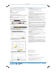
6. Remove the Signal Suppression Tape from the disc to ac vate
the sensor located inside the disc.
ADHESIVE
STRIPS
SIGNAL SUPPRESSION
TAPE
7. Remove the visible protec ve backing material from each
adhesive strip.
8. Align the inner marks on the disc with the magnet on the
sleeve and mount the disc to the grill/stove face.
INNER
MARKS
MAGNET
SLEEVE
9. Install the grill knob back onto the knob stem.
10. Use your Panel to program the Grill Guard.
Programming the Device on the GC2/GC2 Panel
For GC2 and GC3 panels, program the Grill Guard on your 2GIG
panel with the following parameters. (Please refer to your panel’s
quick programming guide for the actual steps.)
Sensor Type: (23) No Response Type
Sensor Equipment Type: Contact
Equipment Code: (0862) 2GIG Thin Door/Window Contact
1
Serial Number: [Input the unique 7-digit TXID.]
2
Equipment Age: New
Sensor Loop Number: 2
Dialer/Transmission Delay:
Enabled
Voice Descriptor: GAS LEFT ON
3
Sensor Reports: Enabled
Sensor Supervised: Disabled
4
Sensor Chime: [User-specifi ed]
1
This is a provisional Equipment Code. A new category called
“Grill Guard” (or similar name) will be added in a future GC2/GC3
panel update.
2
Alterna vely, a Grill Guard can be automa cally learned in.
3
This is a recommended voice descriptor. The user may defi ne a
custom voice descriptor, as needed.
4
Choose Disabled if the user plans on taking the grill/stove
away from the premises from me to me. Otherwise, choose
Enabled.
PRINTER’S INSTRUCTIONS:
INSTR,INSTL GC-GRILL1-B-345 - P/N: 10017336 X16 INK: BLACK - MATERIAL: 16 LB. MEAD BOND - SIZE: 6.000” X 9.000” - TOL: +/- 0.125”- SCALE: 1-1 - FOLDING: 4X TO 1.5” x 2.25” - FINISH WITH LOGO SHOWING - SIDE 1 OF 2