
User's Manual


Power Connection
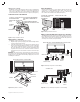
Connect the power adapter (included) to the power terminals (See Figure 7).
Refer to your controller operating instructions to add this device under the
command of the controller.
1. With your controller in Discovery or Add Mode, tap the push button.
2. You should see an indication on your controller that the “device was
added” to the network and the Green LED will blink 3 times.
3. The device will appear in the list of Switches. It should display as a switch.
If the controller shows the addition failed, repeat Steps 1-3.
Adding to a Network
✓ NOTE: If you have trouble adding the GoControl Irrigation Controller to a
group it may be that the Home ID and Node ID were not cleared from it
after testing. You must fi rst “RESET UNIT” to remove it from the network.
Although adding it to a group includes it in the network, removing it from
a group does not remove it from the network. If removed from a group, it
functions as a repeater (only). “RESET UNIT” removes it completely from
the network.
To Reset Unit (If Required):
In the event that your primary controller is lost or otherwise inoperable, to reset
the GoControl Irrigation Controller and clear all network information, follow
these steps:
1. Tap the push button fi ve (5) times.
2. Then press and hold the push button for 15 seconds. The LED will
increasingly blink faster to indicate that a Reset is taking place.
Removing from a Network:
The GoControl Irrigation Controller can be removed from the network by the
controller. Refer to the controller operating instructions for details.
1. Set the controller into Removal Mode and follow its instruction to delete it
from the controller.
2. Remove the switch by tapping the push button 2 times.
3. You should see an indication on your controller that the “device was
removed” from the network and the Green LED will blink 3 times.
LED Status
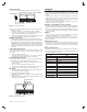
1. Pushing the button on the WI15VZ-1, will get the Irrigation Controller to
associate with the Z-Wave hub (Figure 8).
2. The LED should be red when fi rst powered
✓ NOTE: Before the LED shows solid RED, it may go through a fl ashing
sequence for self test..
3. When the button is pushed it will blink green then alternate between green
and orange, then go solid green.
OPERATION
The WI15Z-1 is designed to run the irrigation system based on your pre-
programmed schedule. Utilizing your Z-Wave hub, you can create this schedule.
It will be saved in the WI15Z-1 and run automatically unless an Interrupt is sent
received.
In the event that your hub does not support schedules, or no schedule is
programmed into the Irrigation Controller, each valve can run independently
and be triggered as part of a scene. See your hub instructions on how to
confi gure the system to operate in this manner.
To trigger a specifi c valve that is connected to the WI15Z-1, use the control
application associated to you Z-Wave hub.
Weather / Optional Water Sensor Interrupt
The WI15Z-1 can take instructions from your Hub to not run the pre-determined
irrigation schedule. In the event that your local weather causes the WI15Z-1 to
not run the re-determined irrigation schedule, the LED will blink red / green for
as long as the valves are supposed to be running. Once the valves are turned
off, it will stop blinking.
All Stop
In the event that you wish to stop the scheduled running of the irrigation
controller, press the User Button on the front of the WI15Z-1.
The LED will blink Orange for 15 seconds. After 15 seconds it will continue to
blink Orange until the user presses the Button again, or the Hub tells it to go
back to normal mode.
Valve Fault Detection
The WI15Z-1 can detect if a valve is disconnected or has damaged or shorted
control wires. In the event that a Fault is detected, the LED will blink Red as
long as the valve is running. Once the valve is turned off, it will stop blinking
Red.
Power Fault Detection
The WI15Z-1 can determine if there is a problem with the power provided by
the power supply. In the event that a Fault is detected, the LED will blink Red/
Orange until the problem is corrected.
Bi-Color LED States
Color Status
Red-On No Hub
Green-On Connected to Hub
Orange-On Stuck Button
Red - Blinking Valve Fault
(open/short
Green - Blinking Searching for Hub
Orange - Blinking Flow Fault (too low/too high)
Red/Green - Toggle Off due to sensors or weather.
Red/Orange - Toggle Power out of range.
Green/Orange - Toggle Communicating with Hub
None No Power
Status Table for LED States
Power
Common
Master
Valve/Pump
Pressure
Flow
Moisture
Rain
234
5
6
78 9
10
11 12
13
1
14
15
Valves
FRONT VIEW OF WI15VZ-1 CONTROL PANEL
POWER ADAPTOR
Copyright © 2015 Nortek Security & Control LLC
Power
Common
Master
Valve/Pump
Pressure
Flow
Moisture
Rain
234
5
6
78 9
10
11 12
13
1
14
15
Valves
STATUS
BUTTON
BI-COLOR LED
RED LED
Figure 7. Connecting Power Adaptor
Figure 8. LED Status/Button Location