
User's Manual

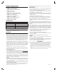

Wiring to the Controller
The WI15VZ-1 Controller has 28 terminal connections The recommended wire
used to connect to terminals is in the range of 16 to 22 gauge single strand. To
connect a wire to the terminal, use a small screwdriver or pen. While pushing
in on the terminal block, insert the wire end into receptor hole (See Figure 3).
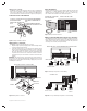
Terminal Connection Identifi cation
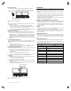
Wiring Valves to Controller
The WI15VZ-1 Controller accommodates up to 15 valves.
1. Begin the wiring sequence by stripping a wire end and inserting it into the
“Common” terminal on the Controller.
2. Connect the Common wire to (1) one of the valves. (For simplicity only two
valves are shown in diagram below. A maximum of 15 valves can be wired
to the controller. Connect the other wire of each valve to a corresponding
wire of the cable bundle. All connections should be made with wire nuts.
To prevent electrical overload one common wire should be connected to
each valve and only one valve should be connected to each station (See
Figure 4).
IMPORTANT: The connection wires can be buried in the ground, however, for
more protection, wires can be fed through PVC pipe then buried. Be sure to avoid
placing wires in the vicinity where future trenching or digging may occur as this
can damage the connections.
Valve Identifi cation
During the valve wiring process, it will be helpful to label the valve name and
location. There is a Valve Identifi cation Label located on the inside of the
WI15VZ-1 front cover (examples: front lawn, roses, grass, southside, drip).
Here is where valve information can be written (See Figure 5).
Wiring of Optional Third Party Components to Controller
The WI15VZ-1 Controller has provisions for a number of additional components.
Each component has two terminal connections. See the fi gure below for more
details. Be sure to run the wires from the terminals, thru the cable guide on the
lower edge of the controller (See Figure 6 and 6A).
Copyright © 2015 Nortek Security & Control LLC
Power
Common
Master
Valve/Pump
Pressure
Flow
Moisture
Rain
2
34
5
6
78 9
10
11 12
13
1
14
15
Valves
FRONT VIEW OF WI15VZ-1 CONTROL PANEL
COMMON
SOLENOID
WIRE NUT
FEED WIRES THRU
CABLE GUIDE
CABLE GUIDE
VALVE 1
VALVE 2
Power
Common
Master
Valve/Pump
Pressure
Flow
Moisture
Rain
234
5
6
78 9
10
11 12
13
1
14
15
Valves
VIEW OF WI15VZ-1 CONTROL PANEL WITHOUT FRONT COVER
0.0
0.0
MASTER
VALVE/OR
RELAY FOR PUMP
PRESSURE
SENSOR
FLOW
SENSOR
MOISTURE
SENSOR
RAIN
SENSOR
CABLE GUIDE
VALVE 1
VALVE 2
VALVE 3
VALVE 4
VALVE 5
VALVE 6
VALVE 7
VALVE 8
VALVE 9
VALVE 10
VALVE 11
VALVE 12
VALVE 13
VALVE 14
VALVE 15
TURN FRONT COVER OVER
FOR CONTROLLER
INFORMATION
INSIDE OF FRONT COVER
VALVE ID WRITE-ON
LABEL
180°
QUICK REFERENCE
GUIDE
PROGRAMMING INSTRUCTIONS
THE UPPER LED SHOWS THE STATUS
LED STATES
COLOR STATUS
RED POWER ON. BUT NO HUB
GREEN CONNECTED TO HUB
ORANGE SWITCH STUCK
BLINK RED VALVE FAULT (OPEN/SHORT)
BLINK GREEN SEARCHING FOR HUB
BLINK ORANGE SHUTOFF MODE
BLACK NO POWER
RED/GREEN OFF DUE TO WEATHER SENSORS
RED/ORANGE INPUT VOLTAGE OUT OF RANGE
GREEN/ORANGE COMMUNICATIONS WITH HUB
THE LOWER LED IS RED WHENEVER ANY VALVE IS ON
THE SWITCH HAS (3) THREE USES:
1. PUSH SWITCH ONCE WHEN STATUS LED IS RED TO
ENROLL THE WI15VZ-1 WITH THE Z-WAVE HUB.
TELL THE HUB YOU ARE GOING TO HAVE WI15VZ-1 JOIN
THE NETWORK FIRST.
2. PUSH SWITCH TWICE WHEN STATUS LED IS GREEN TO
REMOVE THE WI15VZ-1 FROM THE Z-WAVE HUB. TELL
HUB YOU ARE GOING TO HAVE WI15VZ-1 REMOVED FROM
NETWORK FIRST.
3. PUSH THE SWITCH ONCE WHEN THE LOWER LED IS ON (VALVE
ON) TO TURN OFF THAT VALVE AND STOP ANYTHING FROM
HAPPENING UNTIL YOU TELL THE HUB IT IS OK TO RUN AGAIN
Power
Common
Master
Valve/Pump
Pressure
Flow
Moisture
Rain
234
5
6
78 9
10
11 12
13
1
14
Valves
CLOSE-UP OF COMPONENT HOOKUPS
RAIN
SENSOR
MOISTURE
SENSOR
0.0
0.0
FLOW
SENSOR
PRESSURE
SENSOR
MASTER
VALVE/OR
RELAY FOR PUMP
2. PUSH DOWN ON WIRE TERMINAL
WITH SMALL SCREWDRIVER OR
PEN
1. STRIP 1/2" OF INSULATION
FROM WIRE END AND
INSERT IT INTO RECEPTOR
HOLE
TERMINAL
BLOCK
RECEPTOR HOLE
3. INSERT BARE WIRE END INTO
TERMINAL BLOCK RECEPTOR HOL
E
Figure 3. Wiring to Terminal Connection
Figure 4. Wiring Valves to Controller
Figure 5. Wiring to Terminal Connection
Figure 6. Third Party Component to Controller Wiring
Figure 6A. Closeup of Third Party Components to Controller Wiring