
Installation Manual

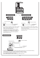


Circulation pump 1
Circulation pump 2
(if necessary)
Relief valve
Hot water
supply points
Hot water supply line
Hot water return line
Cold water supply pipe *1
When installing 2 pumps in parallel
Set “Yes” for the question
“Start pump rotation?” in system settings
(Refer to page 10).
* Size the cold water supply piping to allow for
maximum flow rates of the building.
* Be sure to connect the cold water supply pipe
between the hot water storage tank and intake
side of the storage tank circulation pump.
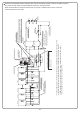
Thermostat
System Controller
Remote
controller
cord
Remote Controller
Remote Controller Cord
Unit 1Unit 2Unit 3Unit 10Unit 11Unit 12
(copper or stainless steel pipe)
Hot water
storage tank
(copper or stainless steel pipe)
Return line
circulation pump
(Size for max. flow)
(Size for max. flow)
Storage tank supply line
(copper or stainless steel pipe)
Storage tank return line
(copper or stainless steel pipe)
Remote Controller
Cord
Pump Control Wires
(use external relays)
Set “Yes” for the question “Pump error check” in the
Sys settings when connecting these wires to system
controller (Refer to page 12).
*
NWC-ADAPTER
(NAW-1 US)
Example of Installation with a Storage Tank and Recirculation System (Tank recirculation system)
The pump will push water through the Multi-unit System to heat up the tank.
When the temperature of the thermostat is high, the system controller will turn off the pump until
the the temperature cools down.
* For the set temperature of the remote controller, use the temperature (of the thermostat) + about 10°F.
* To achieve the highest recovery, size the storage tank circulation pump for maximum capacity.
(9 GPM (each) @ 40 ft. of head (160°F setting or less) + piping losses through the system.)
Verify the supply pressure to the units is at least 30 PSI.
─27─