
User Manual

Operating Characteristics 3-13
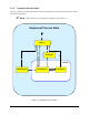
3.3.1 E10 State
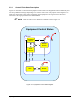
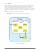
Figure 3-3 illustrates the state of the Equipment in relationship to overall factory production. The E10
state diagram is implemented in the Equipment according to the details specified in the SEMI E10
document. The following summarizes the Equipment’s implementation of the E10 standard:
The Equipment can transition from any state to any other state except for “Productive”. The “Productive”
state can only be entered from the “Standby” state. Upon startup, the Equipment is in “Non-Scheduled
Time”.
E10 states are not available to the host computer via SECS/GEM.
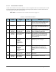
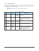
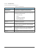
" NOTE Refer to Table 3-9 for definition of numbers used in Figure 3-3.
E10 State
Productive
Non-Productive
Engineering
Scheduled
Downtime
Unscheduled
Downtime
Non-
Scheduled
Downtime
C
2
3
1
Standby
5
4
Figure 3-3 E10 State Diagram