
Manual


9-2 Appendix A
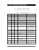
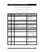
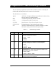
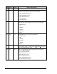
VID Class Format Name and Description
6 EC U2 ESTABLISHCOMMUNICATIONSTIMER. Time in seconds of
how long the equipment will delay after an unsuccessful Connect
Request before sending another. Valid values are 0-32000.
8 EC U1 INITCOMMSTATE. Initial (power-up) Communications State.
0 = Disabled
1 = Enabled
9 EC U1 INITCONTROLSTATE. Initial (power-up) control super-state.
1 = Off-Line
2 = On-Line
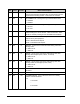
10 EC U2 HEARTBEAT. The time in seconds that the Equipment will delay
before sending S1F1 to test the link. Units are seconds. Valid
values are 0-3200 (a setting of zero will disable the heartbeat).
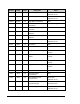
17 EC BOOL RPTYPE. This EC controls some aspects of the format of Event
Reports sent by this Equipment.
FALSE = Normal Event Reports
TRUE = Annotated Event Reports
18 EC U1 WBITS10. An EC which controls the W-Bit setting used when
sending S10F1.
0 = W-Bit not set
1 = W-Bit set
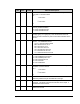
19 EC U1 WBITS5. An EC which controls the W-Bit setting used when
sending Alarm Reports (S5F1, S5F71, or S5F73).
0 = W-Bit not set
1 = W-Bit set
20 EC U1 WBITS6. An EC which controls the W-Bit setting used when
sending stream six messages (events, trace)
0 = W-Bit not set
1 = W-Bit set
21 SV U1 ABORTLEVEL. The AbortLevel of the most recent ABORT
command.
22 SV U4 ALARMID. The ALID of the most recent Alarm transition.
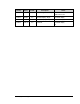
23 SV List ALARMSENABLED. A list of all Alarms which are currently
enabled. Format as follows:
<L,n
1.<U4 ALID>
...
n.<U4 ALID>
>