
Manual


Introduction 1-3
1.1.2 Physical Connection
The GEM hardware interface must be a TCP/IP network card connection through a
Ten-Base-T connector or BNC jack (SECS-II interface).
The following documentation is provided only as a reference for RS-232 connections
(SECS-I interface) and is currently not implemented by FmNT.
The RS-232 connector on the Equipment deviates from the standard SECS-I DB25F
connector.
The GES-1993 provides a male 25-pin RS-232 "DB25M" connector on its backpanel
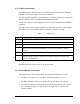
as the SECS port. The following pins on the RS-232 connector are used:
Table 1-1 RS-232 Pins
Pin No. Description
1 Shield.
2 TX Data (Equipment-to-Host).
3 RX Data (Host-to-Equipment).
4 Request to send (RTS). The Equipment raises this output signal when activating
SECS. Not required by SECS standard, but you may find it useful for modem
control.
7 Signal Ground.
20 Data Terminal Ready (DTR). The Equipment raises this output signal when
activating SECS. This is not required by the SECS standard, but you may find it
useful for modem control.
Optional SECS power pins 18 and 25 are not provided.
1.1.3 SECS-I Blocks Transmitted
The Equipment uses the following SECS-I conventions in the blocks it sends:
The Device ID is present in every block, with the R-bit always set to "1".
The Block Number is always one (0x0001) for the first block of a message.
For Primary messages, the System Bytes are generated unique for each message.
For Secondary messages, the System Bytes are replicated from the received
Primary message.