
Owner's manual


3-6 Operating Characteristics
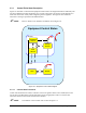
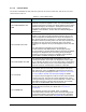
3.3.1 Control Finite State Description
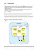
Figure 3-2 and Table 3-5 describe the Equipment Control State. The Equipment behaves differently and
will accept different messages depending on its current control state. The purpose of this diagram is to
make clear to the Host exactly what is happening at the Equipment. The logic for these states and
transitions is the logic specified in the GEM standard.
NOTE Refer to Table 3-5 for definition of numbers used in Figure 3-2.
Equipment Control States
Off-Line
On-Line
C
1
C
C
Remote
Local
C
2
3
5
6
7
8
9
10
11
12
13
14
Equipment
Off-Line
Host
Off-Line
4
Attempt
On-Line
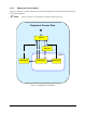
Figure 3-2 Equipment Control State Diagram
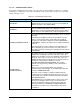
3.3.1.1 Control State Transitions
Certain state transitions will cause a collection event to be signaled. If the event is enabled, this event
will be sent to the Host along with the appropriate reports if appropriate. Table 3-5 lists the state
transitions and notes when events will be sent to the Host.
NOTE The numbers in the # column refer to those in Figure 3-2.