
Owner's manual


1-10 Introduction
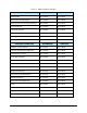
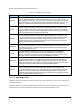
Table 1-6 shows the recommended settings for compatibility with various types of Hosts. Factory
(Default) settings are shown in bold.
Table 1-6 Compatibility Settings
Equipment
Constant
E30-93 GEM
3.1
GEM
3.0
GEM
2.0
GEM
1.7
Non-GEM
CONFIGALARMS 0 2 2 2 1 0
CONFIGCONNECT 2 2 2 1 1 0
CONFIGEVENTS 1 1 1 1 1 0
RPTYPE False False False False False
False
or
True
WBITS5 1 1 or 0 1 or 0 1 or 0 1 or 0 1 or 0
WBITS6 1 1 1 1 1 1 or 0
WBITS10 1 1 or 0 1 or 0 1 or 0 1 or 0 0
CONFIGSPOOL 1 0 0 0 0 0
1.10 State Diagrams
This document uses several Finite State Machine diagrams to describe the current condition of the
Equipment’s SECS link, material handling mechanisms, and process cycle. Each Finite State Machine
diagram includes a State Diagram and a complete description of the states and state transitions.
All Finite State Diagrams have been prepared in the format specified in the GEM standard. This notation
is required as a fundamental part of GEM compliance and must be included in the Equipment SECS
Interface Documentation. This notation is the “Statechart” notation developed by David Harel.
The following are the major characteristics of this notation as it is used in this document:
1. Each state is represented by a rectangle with rounded corners.
2. A collection of sub-states may be grouped into a super-state.
3. The entity described by the diagrams will be in one and only one of the sub-states at all
times.
4. Variables representing the current state of an entity do not contain values for super-states,
only the lowest sub-state is represented.
5. State transitions are represented by single-headed arrows.
6. Each state transition is a Collection Event, and it has a unique Collection Event ID (CEID).
7. An arrow directly from a super-state to another state describes a Collection Event that can
occur while the entity is in any one of the sub-states contained in the super-state.