
Manual


Appendix A – Data Dictionary Variables A-1
Appendix A – Data Dictionary Variables
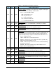
Table A-1 is a summary explanation of the machine variables described in Section 6 sorted by ID number
and containing details of the content of each variable.
The data formats are as follows:
A[nn] ASCII text of length nn. Where two numbers are indicated, they specify a range of
acceptable lengths.
Bool A boolean flag indicating TRUE or FALSE.
F4,F8 A floating point number in four bytes.
I1,I2,I4,I8 Signed integers of the indicated length in bytes.
U1,U2,U4,U8 Unsigned integers of the indicated length in bytes.
List An array of similar structures or primitive elements, as above. The list format is
specified in the description field.
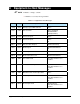
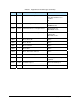
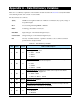
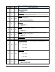
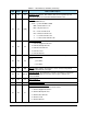
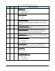
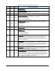
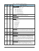
Table A-1 Data Dictionary Variables
VID Class Format Name and Description
1 EC U1
CONFIGALARMS
. An EC which controls which Alarm Report message
this Equipment will send.
0 = S5F1 default
1 = S5F71
2 = S5F73
2 EC U1
CONFIGCONNECT
. An EC which controls which SECS message this
Equipment will use for Connect Request.
0 = S1F1
1 = S1F65
2 = S1F13 default
3 EC U1
CONFIGEVENTS
. An EC which controls some aspects of the Event
Reports sent by this Equipment.
0 = S6F9 or S6F3
1 = S6F11 or S6F13 default
5 EC A[0..22]
DEVICENAME
. The Host can change this EC to define a meaningful
name for the equipment.
6 EC U2
ESTABLISHCOMMUNICATIONSTIMER
. Time in seconds of how long
the equipment will delay after an unsuccessful Connect Request before
sending another. Valid values are 0-32000.
8 EC U1
INITCOMMSTATE
. Initial (power-up) Communications State.
0 = Disabled
1 = Enabled