
Owner's manual
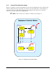
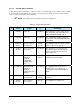
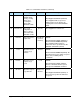
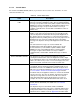
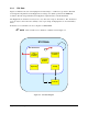
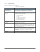
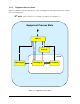
Table Of Contents
- Title Page
- Table of Contents
- 1. Introduction
- 2. Message Summary
- 3. Operating Characteristics
- 4. SECS Message Detail
- 4.1 SML Notation
- 4.2 SECS Messages
- S1F1 - Are You There
- S1F2 - On Line Data (Equipment to Host)
- S1F2 - On Line Data (Host to Equipment)
- S1F3 - Selected Status Request
- S1F4 - Selected Status Data
- S1F11 - Status Variable Namelist Request
- S1F12 - Status Variable Namelist Reply
- S1F13 - Connect Request
- S1F14 - Connect Request Acknowledge
- S1F15 - Request Off-Line
- S1F16 - Off-Line Acknowledge
- S1F17 - Request On-Line
- S1F18 - On-Line Acknowledge
- S1F65 - Connect Request
- S1F66 - Connect Request Acknowledge
- S2F13 - Equipment Constant Request
- S2F14 - Equipment Constant Data
- S2F15 - New Equipment Constant Send
- S2F16 - Equipment Constant Send Acknowledge
- S2F17 - Date and Time Request
- S2F18 - Date and Time Data
- S2F23 - Trace Initialize Send
- S2F24 - Trace Initialize Acknowledge
- S2F25 - Diagnostic Loopback Request
- S2F26 - Diagnostic Loopback Data
- S2F27 - Initiate Process Request
- S2F28 - Initiate Process Acknowledge
- S2F29 - Equipment Constant Namelist Request
- S2F30 - Equipment Constant Namelist Reply
- S2F31 - Date and Time Send
- S2F32 - Date and Time Acknowledge
- S2F33 - Define Report
- S2F34 - Define Report Acknowledge
- S2F35 - Link Event Report
- S2F36 - Link Event Report Acknowledge
- S2F37 - Enable/Disable Event Report
- S2F38 - Enable/Disable Event Report Acknowledge
- S2F39 - Multi-Block Inquire
- S2F40 - Multi-Block Grant
- S2F41 - Remote Command with Parameters
- S2F42 - Remote Command Acknowledge
- S2F43 - Reset Spooling Streams and Functions
- S2F44 - Reset Spooling Acknowledge
- S2F45 - Define Variable Limits Attributes
- S2F46 - Variable Limit Attribute Acknowledge
- S2F47 - Variable Limit Attribute Request
- S2F48 - Variable Limit Attributes Send
- S5F1 - Alarm Report
- S5F2 - Alarm Acknowledge
- S5F3 - Enable/Disable Alarm Send
- S5F4 - Enable/Disable Alarm Acknowledge
- S5F5 - List Alarms Request
- S5F6 - List Alarm Data
- S5F7 - List Enabled Alarms Request
- S5F8 - List Enabled Alarm Data
- S5F71 - Alarm Report Block Send
- S5F72 - Alarm Report Block Acknowledge
- S5F73 - Alarm Report Block Acknowledge
- S5F74 - Alarm Notification Acknowledge
- S6F1 - Trace Data Send
- S6F2 - Trace Data Acknowledge
- S6F3 - Annotated Event Report
- S6F4 - Annotated Event Report Acknowledge
- S6F5 - Multi-Block Data Send Inquire
- S6F6 - Multi-Block Grant
- S6F9 - Event Report
- S6F10 - Event Report Acknowledge
- S6F11 - Event Report Send
- S6F12 - Event Report Acknowledge
- S6F13 - Annotated Event Report Send
- S6F14 - Annotated Event Report Acknowledge
- S6F15 - Event Report Request
- S6F16 - Event Report Data
- S6F17 - Annotated Event Report Request
- S6F18 - Annotated Event Report Data
- S6F19 - Request Report Request
- S6F20 - Request Report Data
- S6F21 - Request Annotated Report Request
- S6F22 - Request Annotated Report Data
- S6F23 - Request Spooled Data
- S6F24 - Request Spooled Data Acknowledge
- S7F1 - Process Program Load Inquire
- S7F2 - Process Program Load Grant
- S7F3 - Process Program Send
- S7F4 - Process Program Acknowledge
- S7F5 - Process Program Request
- S7F6 - Process Program Data
- S7F17 - Process Program Delete
- S7F18 - Process Program Delete Acknowledge
- S7F19 - Process Program Directory Request
- S7F20 - Process Program Directory
- S9F1 - Unrecognized Device ID
- S9F3 - Unrecognized Stream
- S9F5 - Unrecognized Function
- S9F7 Invalid Data
- S9F9 Transaction Timer Timeout
- S9F11 - Data Too Long
- S10F1 - Terminal Request
- S10F2 - Terminal Request Acknowledge
- S10F3 - Terminal Display, Single
- S10F4 - Terminal Display Single Acknowledge
- S10F5 - Terminal Display, Multiblock
- S10F6 - Terminal Display Multiblock Acknowledge
- S10F9 - Broadcast
- S10F10 - Broadcast Acknowledge
- 5. SECS Scenarios
- 5.1 Equipment Communications
- Equipment Establishes Communications
- Host Establishes Communications
- Simultaneous Establish Communications
- Losing Connection, Re-Connecting
- Heartbeat
- Host Initializes Event Reporting
- Equipment Reports Event
- Equipment Reports Annotated Event
- Host Initiates Trace
- Host Terminates Trace
- Host Requests Status
- Host Defines Limits
- Host Queries Defined Limits
- Host Requests Report by CEID
- Host Requests Annotated Report by CEID
- Host Requests Report by RPTID
- Host Requests Annotated Report by RPTID
- Are You There
- Host Reads Equipment Constants
- Host Sets Equipment Constants
- 5.2 Data Collection
- 5.3 Alarms
- 5.4 Control State
- 5.5 Process Program Management
- 5.6 Equipment Terminal Communications
- 5.7 SECS Error Messages
- 5.8 Clock
- 5.9 Spooling
- 5.1 Equipment Communications
- 6. Machine Variable Definitions
- 7. Host-to-Equipment Messages
- 8. Equipment-to-Host Messages
- Appendixes
- Glossary
Equipment-to-Host Messages 3-7
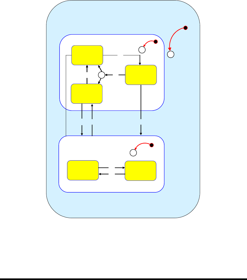
3.2.1 Control Finite State Description
Figure 3-2 and Table 3-5 describe the Equipment Control State. The Equipment behaves differently and
will accept different messages depending on its current control state. The purpose of this diagram is to
make clear to the Host exactly what is happening at the Equipment. The logic for these states and
transitions is the logic specified in the GEM standard.
"
NOTE Refer to Table 3-5 for definition of numbers used in Figure 3-2.
Equipment Control States
Off-Line
On-Line
C
1
C
C
Remote
Local
C
2
3
5
6
7
89
10
11
12
13
14
Equipment
Off-Line
Host
Off-Line
4
Attempt
On-Line
Figure 3-2 Equipment Control State Diagram