
Owner's manual
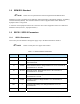
Table Of Contents
- Title Page
- Table of Contents
- 1. Introduction
- 2. Message Summary
- 3. Operating Characteristics
- 4. SECS Message Detail
- 4.1 SML Notation
- 4.2 SECS Messages
- S1F1 - Are You There
- S1F2 - On Line Data (Equipment to Host)
- S1F2 - On Line Data (Host to Equipment)
- S1F3 - Selected Status Request
- S1F4 - Selected Status Data
- S1F11 - Status Variable Namelist Request
- S1F12 - Status Variable Namelist Reply
- S1F13 - Connect Request
- S1F14 - Connect Request Acknowledge
- S1F15 - Request Off-Line
- S1F16 - Off-Line Acknowledge
- S1F17 - Request On-Line
- S1F18 - On-Line Acknowledge
- S1F65 - Connect Request
- S1F66 - Connect Request Acknowledge
- S2F13 - Equipment Constant Request
- S2F14 - Equipment Constant Data
- S2F15 - New Equipment Constant Send
- S2F16 - Equipment Constant Send Acknowledge
- S2F17 - Date and Time Request
- S2F18 - Date and Time Data
- S2F23 - Trace Initialize Send
- S2F24 - Trace Initialize Acknowledge
- S2F25 - Diagnostic Loopback Request
- S2F26 - Diagnostic Loopback Data
- S2F27 - Initiate Process Request
- S2F28 - Initiate Process Acknowledge
- S2F29 - Equipment Constant Namelist Request
- S2F30 - Equipment Constant Namelist Reply
- S2F31 - Date and Time Send
- S2F32 - Date and Time Acknowledge
- S2F33 - Define Report
- S2F34 - Define Report Acknowledge
- S2F35 - Link Event Report
- S2F36 - Link Event Report Acknowledge
- S2F37 - Enable/Disable Event Report
- S2F38 - Enable/Disable Event Report Acknowledge
- S2F39 - Multi-Block Inquire
- S2F40 - Multi-Block Grant
- S2F41 - Remote Command with Parameters
- S2F42 - Remote Command Acknowledge
- S2F43 - Reset Spooling Streams and Functions
- S2F44 - Reset Spooling Acknowledge
- S2F45 - Define Variable Limits Attributes
- S2F46 - Variable Limit Attribute Acknowledge
- S2F47 - Variable Limit Attribute Request
- S2F48 - Variable Limit Attributes Send
- S5F1 - Alarm Report
- S5F2 - Alarm Acknowledge
- S5F3 - Enable/Disable Alarm Send
- S5F4 - Enable/Disable Alarm Acknowledge
- S5F5 - List Alarms Request
- S5F6 - List Alarm Data
- S5F7 - List Enabled Alarms Request
- S5F8 - List Enabled Alarm Data
- S5F71 - Alarm Report Block Send
- S5F72 - Alarm Report Block Acknowledge
- S5F73 - Alarm Report Block Acknowledge
- S5F74 - Alarm Notification Acknowledge
- S6F1 - Trace Data Send
- S6F2 - Trace Data Acknowledge
- S6F3 - Annotated Event Report
- S6F4 - Annotated Event Report Acknowledge
- S6F5 - Multi-Block Data Send Inquire
- S6F6 - Multi-Block Grant
- S6F9 - Event Report
- S6F10 - Event Report Acknowledge
- S6F11 - Event Report Send
- S6F12 - Event Report Acknowledge
- S6F13 - Annotated Event Report Send
- S6F14 - Annotated Event Report Acknowledge
- S6F15 - Event Report Request
- S6F16 - Event Report Data
- S6F17 - Annotated Event Report Request
- S6F18 - Annotated Event Report Data
- S6F19 - Request Report Request
- S6F20 - Request Report Data
- S6F21 - Request Annotated Report Request
- S6F22 - Request Annotated Report Data
- S6F23 - Request Spooled Data
- S6F24 - Request Spooled Data Acknowledge
- S7F1 - Process Program Load Inquire
- S7F2 - Process Program Load Grant
- S7F3 - Process Program Send
- S7F4 - Process Program Acknowledge
- S7F5 - Process Program Request
- S7F6 - Process Program Data
- S7F17 - Process Program Delete
- S7F18 - Process Program Delete Acknowledge
- S7F19 - Process Program Directory Request
- S7F20 - Process Program Directory
- S9F1 - Unrecognized Device ID
- S9F3 - Unrecognized Stream
- S9F5 - Unrecognized Function
- S9F7 Invalid Data
- S9F9 Transaction Timer Timeout
- S9F11 - Data Too Long
- S10F1 - Terminal Request
- S10F2 - Terminal Request Acknowledge
- S10F3 - Terminal Display, Single
- S10F4 - Terminal Display Single Acknowledge
- S10F5 - Terminal Display, Multiblock
- S10F6 - Terminal Display Multiblock Acknowledge
- S10F9 - Broadcast
- S10F10 - Broadcast Acknowledge
- 5. SECS Scenarios
- 5.1 Equipment Communications
- Equipment Establishes Communications
- Host Establishes Communications
- Simultaneous Establish Communications
- Losing Connection, Re-Connecting
- Heartbeat
- Host Initializes Event Reporting
- Equipment Reports Event
- Equipment Reports Annotated Event
- Host Initiates Trace
- Host Terminates Trace
- Host Requests Status
- Host Defines Limits
- Host Queries Defined Limits
- Host Requests Report by CEID
- Host Requests Annotated Report by CEID
- Host Requests Report by RPTID
- Host Requests Annotated Report by RPTID
- Are You There
- Host Reads Equipment Constants
- Host Sets Equipment Constants
- 5.2 Data Collection
- 5.3 Alarms
- 5.4 Control State
- 5.5 Process Program Management
- 5.6 Equipment Terminal Communications
- 5.7 SECS Error Messages
- 5.8 Clock
- 5.9 Spooling
- 5.1 Equipment Communications
- 6. Machine Variable Definitions
- 7. Host-to-Equipment Messages
- 8. Equipment-to-Host Messages
- Appendixes
- Glossary

1.10 State Diagrams
This document uses several Finite State Machine diagrams to describe the current condition of the
Equipment’s SECS link, material handling mechanisms, and process cycle. Each Finite State Machine
diagram includes a State Diagram and a complete description of the states and state transitions.
All Finite State Diagrams have been prepared in the format specified in the GEM standard. This notation
is required as a fundamental part of GEM compliance and must be included in the Equipment SECS
Interface Documentation. This notation is the “Statechart” notation developed by David Harel.
The following are the major characteristics of this notation as it is used in this document:
A. Each state is represented by a rectangle with rounded corners.
B. A collection of sub-states may be grouped into a super-state.
C. The entity described by the diagrams will be in one and only one of the sub-states at
all times.
D. Variables representing the current state of an entity do not contain values for super-
states, only the lowest sub-state is represented.
E. State transitions are represented by single-headed arrows.
F. Each state transition is a Collection Event, and it has a unique Collection Event ID
(CEID).
G. An arrow directly from a super-state to another state describes a Collection Event that
can occur while the entity is in any one of the sub-states contained in the super-state.
H. An arrow directly into a super-state to the
H* (history) symbol describes a transition to
the lowest sub-state which described the entity just before the transition out of the
super-state.
I. An arrow directly into a super-state to the C (conditional) symbol describes a
transition to a particular sub-state based on some other relevant data. The conditional
data is not represented in the diagram but is described in the associated text.
1-14 Equipment-to-Host Messages