
Owner's manual
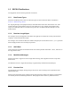
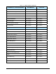
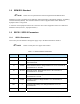

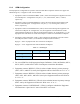
Table Of Contents
- Title Page
- Table of Contents
- 1. Introduction
- 2. Message Summary
- 3. Operating Characteristics
- 4. SECS Message Detail
- 4.1 SML Notation
- 4.2 SECS Messages
- S1F1 - Are You There
- S1F2 - On Line Data (Equipment to Host)
- S1F2 - On Line Data (Host to Equipment)
- S1F3 - Selected Status Request
- S1F4 - Selected Status Data
- S1F11 - Status Variable Namelist Request
- S1F12 - Status Variable Namelist Reply
- S1F13 - Connect Request
- S1F14 - Connect Request Acknowledge
- S1F15 - Request Off-Line
- S1F16 - Off-Line Acknowledge
- S1F17 - Request On-Line
- S1F18 - On-Line Acknowledge
- S1F65 - Connect Request
- S1F66 - Connect Request Acknowledge
- S2F13 - Equipment Constant Request
- S2F14 - Equipment Constant Data
- S2F15 - New Equipment Constant Send
- S2F16 - Equipment Constant Send Acknowledge
- S2F17 - Date and Time Request
- S2F18 - Date and Time Data
- S2F23 - Trace Initialize Send
- S2F24 - Trace Initialize Acknowledge
- S2F25 - Diagnostic Loopback Request
- S2F26 - Diagnostic Loopback Data
- S2F27 - Initiate Process Request
- S2F28 - Initiate Process Acknowledge
- S2F29 - Equipment Constant Namelist Request
- S2F30 - Equipment Constant Namelist Reply
- S2F31 - Date and Time Send
- S2F32 - Date and Time Acknowledge
- S2F33 - Define Report
- S2F34 - Define Report Acknowledge
- S2F35 - Link Event Report
- S2F36 - Link Event Report Acknowledge
- S2F37 - Enable/Disable Event Report
- S2F38 - Enable/Disable Event Report Acknowledge
- S2F39 - Multi-Block Inquire
- S2F40 - Multi-Block Grant
- S2F41 - Remote Command with Parameters
- S2F42 - Remote Command Acknowledge
- S2F43 - Reset Spooling Streams and Functions
- S2F44 - Reset Spooling Acknowledge
- S2F45 - Define Variable Limits Attributes
- S2F46 - Variable Limit Attribute Acknowledge
- S2F47 - Variable Limit Attribute Request
- S2F48 - Variable Limit Attributes Send
- S5F1 - Alarm Report
- S5F2 - Alarm Acknowledge
- S5F3 - Enable/Disable Alarm Send
- S5F4 - Enable/Disable Alarm Acknowledge
- S5F5 - List Alarms Request
- S5F6 - List Alarm Data
- S5F7 - List Enabled Alarms Request
- S5F8 - List Enabled Alarm Data
- S5F71 - Alarm Report Block Send
- S5F72 - Alarm Report Block Acknowledge
- S5F73 - Alarm Report Block Acknowledge
- S5F74 - Alarm Notification Acknowledge
- S6F1 - Trace Data Send
- S6F2 - Trace Data Acknowledge
- S6F3 - Annotated Event Report
- S6F4 - Annotated Event Report Acknowledge
- S6F5 - Multi-Block Data Send Inquire
- S6F6 - Multi-Block Grant
- S6F9 - Event Report
- S6F10 - Event Report Acknowledge
- S6F11 - Event Report Send
- S6F12 - Event Report Acknowledge
- S6F13 - Annotated Event Report Send
- S6F14 - Annotated Event Report Acknowledge
- S6F15 - Event Report Request
- S6F16 - Event Report Data
- S6F17 - Annotated Event Report Request
- S6F18 - Annotated Event Report Data
- S6F19 - Request Report Request
- S6F20 - Request Report Data
- S6F21 - Request Annotated Report Request
- S6F22 - Request Annotated Report Data
- S6F23 - Request Spooled Data
- S6F24 - Request Spooled Data Acknowledge
- S7F1 - Process Program Load Inquire
- S7F2 - Process Program Load Grant
- S7F3 - Process Program Send
- S7F4 - Process Program Acknowledge
- S7F5 - Process Program Request
- S7F6 - Process Program Data
- S7F17 - Process Program Delete
- S7F18 - Process Program Delete Acknowledge
- S7F19 - Process Program Directory Request
- S7F20 - Process Program Directory
- S9F1 - Unrecognized Device ID
- S9F3 - Unrecognized Stream
- S9F5 - Unrecognized Function
- S9F7 Invalid Data
- S9F9 Transaction Timer Timeout
- S9F11 - Data Too Long
- S10F1 - Terminal Request
- S10F2 - Terminal Request Acknowledge
- S10F3 - Terminal Display, Single
- S10F4 - Terminal Display Single Acknowledge
- S10F5 - Terminal Display, Multiblock
- S10F6 - Terminal Display Multiblock Acknowledge
- S10F9 - Broadcast
- S10F10 - Broadcast Acknowledge
- 5. SECS Scenarios
- 5.1 Equipment Communications
- Equipment Establishes Communications
- Host Establishes Communications
- Simultaneous Establish Communications
- Losing Connection, Re-Connecting
- Heartbeat
- Host Initializes Event Reporting
- Equipment Reports Event
- Equipment Reports Annotated Event
- Host Initiates Trace
- Host Terminates Trace
- Host Requests Status
- Host Defines Limits
- Host Queries Defined Limits
- Host Requests Report by CEID
- Host Requests Annotated Report by CEID
- Host Requests Report by RPTID
- Host Requests Annotated Report by RPTID
- Are You There
- Host Reads Equipment Constants
- Host Sets Equipment Constants
- 5.2 Data Collection
- 5.3 Alarms
- 5.4 Control State
- 5.5 Process Program Management
- 5.6 Equipment Terminal Communications
- 5.7 SECS Error Messages
- 5.8 Clock
- 5.9 Spooling
- 5.1 Equipment Communications
- 6. Machine Variable Definitions
- 7. Host-to-Equipment Messages
- 8. Equipment-to-Host Messages
- Appendixes
- Glossary
1.4.2 Physical Connection
The GEM hardware interface must be a TCP/IP network card connection through a Ten-Base-T connector
or BNC jack (SECS-II interface).
NOTE The following information is provided only as a reference for RS-232 connections
(SECS-I interface) and is currently not implemented by FmNT:
• The RS-232 connector on the Equipment deviates from the standard SECS-I DB25F
connector.
• The Equipment provides a male 25-pin RS-232 “DB25M” connector on its back
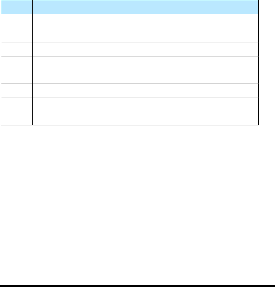
panel as the SECS port. Table 1-2 lists the pins used on the RS-232 connector.
Table 1-2 RS-232 Pins
Pin No. Description
1 Shield.
2 TX Data (Equipment-to-Host).
3 RX Data (Host-to-Equipment).
4 Request to send (RTS). The Equipment raises this output signal when activating
SECS. Not required by SECS standard, but you may find it useful for modem
control.
7 Signal Ground.
20 Data Terminal Ready (DTR). The Equipment raises this output signal when
activating SECS. This is not required by the SECS standard, but you may find it
useful for modem control.
Note: Optional SECS power pins 18 and 25 are not provided.
1.4.3 SECS-I Blocks Transmitted
The Equipment uses the following SECS-I conventions in the blocks it sends:
• The Device ID is present in every block, with the R-bit always set to “1”.
• The Block Number is always one (0x0001) for the first block of a message.
• For Primary messages, the System Bytes are generated unique for each message. For
Secondary messages, the System Bytes are replicated from the received Primary message.
• SECS-I Blocks Received
Blocks received by the Equipment should be formatted as described above (except with the R-bit set
to “0”), although the rules are more relaxed:
If a message consists of a single block, the Block Number may be zero (0x0000) or one (0x0001).
The Equipment is indifferent to the R-bit setting.
Equipment-to-Host Messages 1-5