
Owner's manual
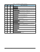

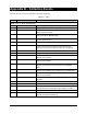
Table Of Contents
- Title Page
- Table of Contents
- 1. Introduction
- 2. Message Summary
- 3. Operating Characteristics
- 4. SECS Message Detail
- 4.1 SML Notation
- 4.2 SECS Messages
- S1F1 - Are You There
- S1F2 - On Line Data (Equipment to Host)
- S1F2 - On Line Data (Host to Equipment)
- S1F3 - Selected Status Request
- S1F4 - Selected Status Data
- S1F11 - Status Variable Namelist Request
- S1F12 - Status Variable Namelist Reply
- S1F13 - Connect Request
- S1F14 - Connect Request Acknowledge
- S1F15 - Request Off-Line
- S1F16 - Off-Line Acknowledge
- S1F17 - Request On-Line
- S1F18 - On-Line Acknowledge
- S1F65 - Connect Request
- S1F66 - Connect Request Acknowledge
- S2F13 - Equipment Constant Request
- S2F14 - Equipment Constant Data
- S2F15 - New Equipment Constant Send
- S2F16 - Equipment Constant Send Acknowledge
- S2F17 - Date and Time Request
- S2F18 - Date and Time Data
- S2F23 - Trace Initialize Send
- S2F24 - Trace Initialize Acknowledge
- S2F25 - Diagnostic Loopback Request
- S2F26 - Diagnostic Loopback Data
- S2F27 - Initiate Process Request
- S2F28 - Initiate Process Acknowledge
- S2F29 - Equipment Constant Namelist Request
- S2F30 - Equipment Constant Namelist Reply
- S2F31 - Date and Time Send
- S2F32 - Date and Time Acknowledge
- S2F33 - Define Report
- S2F34 - Define Report Acknowledge
- S2F35 - Link Event Report
- S2F36 - Link Event Report Acknowledge
- S2F37 - Enable/Disable Event Report
- S2F38 - Enable/Disable Event Report Acknowledge
- S2F39 - Multi-Block Inquire
- S2F40 - Multi-Block Grant
- S2F41 - Remote Command with Parameters
- S2F42 - Remote Command Acknowledge
- S2F43 - Reset Spooling Streams and Functions
- S2F44 - Reset Spooling Acknowledge
- S2F45 - Define Variable Limits Attributes
- S2F46 - Variable Limit Attribute Acknowledge
- S2F47 - Variable Limit Attribute Request
- S2F48 - Variable Limit Attributes Send
- S5F1 - Alarm Report
- S5F2 - Alarm Acknowledge
- S5F3 - Enable/Disable Alarm Send
- S5F4 - Enable/Disable Alarm Acknowledge
- S5F5 - List Alarms Request
- S5F6 - List Alarm Data
- S5F7 - List Enabled Alarms Request
- S5F8 - List Enabled Alarm Data
- S5F71 - Alarm Report Block Send
- S5F72 - Alarm Report Block Acknowledge
- S5F73 - Alarm Report Block Acknowledge
- S5F74 - Alarm Notification Acknowledge
- S6F1 - Trace Data Send
- S6F2 - Trace Data Acknowledge
- S6F3 - Annotated Event Report
- S6F4 - Annotated Event Report Acknowledge
- S6F5 - Multi-Block Data Send Inquire
- S6F6 - Multi-Block Grant
- S6F9 - Event Report
- S6F10 - Event Report Acknowledge
- S6F11 - Event Report Send
- S6F12 - Event Report Acknowledge
- S6F13 - Annotated Event Report Send
- S6F14 - Annotated Event Report Acknowledge
- S6F15 - Event Report Request
- S6F16 - Event Report Data
- S6F17 - Annotated Event Report Request
- S6F18 - Annotated Event Report Data
- S6F19 - Request Report Request
- S6F20 - Request Report Data
- S6F21 - Request Annotated Report Request
- S6F22 - Request Annotated Report Data
- S6F23 - Request Spooled Data
- S6F24 - Request Spooled Data Acknowledge
- S7F1 - Process Program Load Inquire
- S7F2 - Process Program Load Grant
- S7F3 - Process Program Send
- S7F4 - Process Program Acknowledge
- S7F5 - Process Program Request
- S7F6 - Process Program Data
- S7F17 - Process Program Delete
- S7F18 - Process Program Delete Acknowledge
- S7F19 - Process Program Directory Request
- S7F20 - Process Program Directory
- S9F1 - Unrecognized Device ID
- S9F3 - Unrecognized Stream
- S9F5 - Unrecognized Function
- S9F7 Invalid Data
- S9F9 Transaction Timer Timeout
- S9F11 - Data Too Long
- S10F1 - Terminal Request
- S10F2 - Terminal Request Acknowledge
- S10F3 - Terminal Display, Single
- S10F4 - Terminal Display Single Acknowledge
- S10F5 - Terminal Display, Multiblock
- S10F6 - Terminal Display Multiblock Acknowledge
- S10F9 - Broadcast
- S10F10 - Broadcast Acknowledge
- 5. SECS Scenarios
- 5.1 Equipment Communications
- Equipment Establishes Communications
- Host Establishes Communications
- Simultaneous Establish Communications
- Losing Connection, Re-Connecting
- Heartbeat
- Host Initializes Event Reporting
- Equipment Reports Event
- Equipment Reports Annotated Event
- Host Initiates Trace
- Host Terminates Trace
- Host Requests Status
- Host Defines Limits
- Host Queries Defined Limits
- Host Requests Report by CEID
- Host Requests Annotated Report by CEID
- Host Requests Report by RPTID
- Host Requests Annotated Report by RPTID
- Are You There
- Host Reads Equipment Constants
- Host Sets Equipment Constants
- 5.2 Data Collection
- 5.3 Alarms
- 5.4 Control State
- 5.5 Process Program Management
- 5.6 Equipment Terminal Communications
- 5.7 SECS Error Messages
- 5.8 Clock
- 5.9 Spooling
- 5.1 Equipment Communications
- 6. Machine Variable Definitions
- 7. Host-to-Equipment Messages
- 8. Equipment-to-Host Messages
- Appendixes
- Glossary
A-8 Appendix A – Data Dictionary Values
Table A-1 Data Dictionary Variables (continued)
VID Class Format Name and Description
302 SV A[14] FluidThawTime1. This is the time stamp in the YYYYMMDDhhmmss
format, at which the fluid was removed from the refrigerator and began to
warm up. Similar to the TIME(39) variable format.
YYYY = year from 0000 to 9999
MM = month from 01 to 12
DD = day from 01 to 31
hh = hours from 00 to 59
mm = minutes from 00 to 59
ss = seconds from 00 to 59
303 SV A[12] FluidFileName2. This is the name of the file containing the dispensing
fluid data for Valve 2. See FluidFileName1 (VID 300) for a detailed
description.
304 SV A[20] FluidLotNumber2. This is the dispensing fluid lot number for Valve 2. See
FluidLotNumber1 (VID 301) for a detailed description.
305 SV A[14] FluidThawTime2. This is the time stamp for the fluid for Valve 2. See
FluidThawTime1 (VID 302) for a detailed description.
306 DV A[10] FluidState1. Fluid level of syringe on Valve 1as reported by the low fluid
sensor or fluid level monitoring software. This value is updated twice per
board. Once when the board is loaded and ready for dispensing and
again when dispensing is complete on that board. Possible values are:
“FULL” – Fluid level is full.
“LOW” – Fluid level has reached the low level.
“EMPTY” – Fluid level is close to empty. This value is possible only
with the two position hardware sensor.
“NONE” – Fluid sensing sensors do not exist or software monitoring
has not been turned on.
“ERROR” – Error when using the two position hardware sensor.
Signals indicate empty but not low.
307 DV A[10] FluidState2. Same as FluidState1 but for Valve 2.
350 DV A[30] BarcodeRaw. The barcode string exactly as it is read by the scanner
from the barcode tag on the board at the dispense station.
351 DV A[30] BarcodeFiltered. The barcode string read in from the scanner after
unwanted characters are filtered out as specified by the Operator.
400 DV F8 FlowRate1. The most current fluid flow rate for Valve 1 in mg./sec.
401 DV F8 FlowRateMin1. The minimum flow rate for Valve 1 in mg./sec. allowed
during this run.
402 DV F8 FlowRateMax1.The maximum flow rate for Valve 1 in mg./sec. allowed
during this run.
403 DV F8 FlowRate2. The most current fluid flow rate for Valve 2 in mg/sec.