
Owner's manual
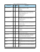
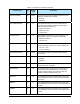
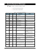
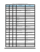
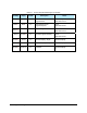

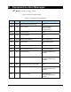
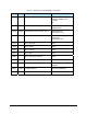
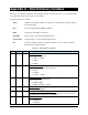
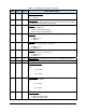
Table Of Contents
- Title Page
- Table of Contents
- 1. Introduction
- 2. Message Summary
- 3. Operating Characteristics
- 4. SECS Message Detail
- 4.1 SML Notation
- 4.2 SECS Messages
- S1F1 - Are You There
- S1F2 - On Line Data (Equipment to Host)
- S1F2 - On Line Data (Host to Equipment)
- S1F3 - Selected Status Request
- S1F4 - Selected Status Data
- S1F11 - Status Variable Namelist Request
- S1F12 - Status Variable Namelist Reply
- S1F13 - Connect Request
- S1F14 - Connect Request Acknowledge
- S1F15 - Request Off-Line
- S1F16 - Off-Line Acknowledge
- S1F17 - Request On-Line
- S1F18 - On-Line Acknowledge
- S1F65 - Connect Request
- S1F66 - Connect Request Acknowledge
- S2F13 - Equipment Constant Request
- S2F14 - Equipment Constant Data
- S2F15 - New Equipment Constant Send
- S2F16 - Equipment Constant Send Acknowledge
- S2F17 - Date and Time Request
- S2F18 - Date and Time Data
- S2F23 - Trace Initialize Send
- S2F24 - Trace Initialize Acknowledge
- S2F25 - Diagnostic Loopback Request
- S2F26 - Diagnostic Loopback Data
- S2F27 - Initiate Process Request
- S2F28 - Initiate Process Acknowledge
- S2F29 - Equipment Constant Namelist Request
- S2F30 - Equipment Constant Namelist Reply
- S2F31 - Date and Time Send
- S2F32 - Date and Time Acknowledge
- S2F33 - Define Report
- S2F34 - Define Report Acknowledge
- S2F35 - Link Event Report
- S2F36 - Link Event Report Acknowledge
- S2F37 - Enable/Disable Event Report
- S2F38 - Enable/Disable Event Report Acknowledge
- S2F39 - Multi-Block Inquire
- S2F40 - Multi-Block Grant
- S2F41 - Remote Command with Parameters
- S2F42 - Remote Command Acknowledge
- S2F43 - Reset Spooling Streams and Functions
- S2F44 - Reset Spooling Acknowledge
- S2F45 - Define Variable Limits Attributes
- S2F46 - Variable Limit Attribute Acknowledge
- S2F47 - Variable Limit Attribute Request
- S2F48 - Variable Limit Attributes Send
- S5F1 - Alarm Report
- S5F2 - Alarm Acknowledge
- S5F3 - Enable/Disable Alarm Send
- S5F4 - Enable/Disable Alarm Acknowledge
- S5F5 - List Alarms Request
- S5F6 - List Alarm Data
- S5F7 - List Enabled Alarms Request
- S5F8 - List Enabled Alarm Data
- S5F71 - Alarm Report Block Send
- S5F72 - Alarm Report Block Acknowledge
- S5F73 - Alarm Report Block Acknowledge
- S5F74 - Alarm Notification Acknowledge
- S6F1 - Trace Data Send
- S6F2 - Trace Data Acknowledge
- S6F3 - Annotated Event Report
- S6F4 - Annotated Event Report Acknowledge
- S6F5 - Multi-Block Data Send Inquire
- S6F6 - Multi-Block Grant
- S6F9 - Event Report
- S6F10 - Event Report Acknowledge
- S6F11 - Event Report Send
- S6F12 - Event Report Acknowledge
- S6F13 - Annotated Event Report Send
- S6F14 - Annotated Event Report Acknowledge
- S6F15 - Event Report Request
- S6F16 - Event Report Data
- S6F17 - Annotated Event Report Request
- S6F18 - Annotated Event Report Data
- S6F19 - Request Report Request
- S6F20 - Request Report Data
- S6F21 - Request Annotated Report Request
- S6F22 - Request Annotated Report Data
- S6F23 - Request Spooled Data
- S6F24 - Request Spooled Data Acknowledge
- S7F1 - Process Program Load Inquire
- S7F2 - Process Program Load Grant
- S7F3 - Process Program Send
- S7F4 - Process Program Acknowledge
- S7F5 - Process Program Request
- S7F6 - Process Program Data
- S7F17 - Process Program Delete
- S7F18 - Process Program Delete Acknowledge
- S7F19 - Process Program Directory Request
- S7F20 - Process Program Directory
- S9F1 - Unrecognized Device ID
- S9F3 - Unrecognized Stream
- S9F5 - Unrecognized Function
- S9F7 Invalid Data
- S9F9 Transaction Timer Timeout
- S9F11 - Data Too Long
- S10F1 - Terminal Request
- S10F2 - Terminal Request Acknowledge
- S10F3 - Terminal Display, Single
- S10F4 - Terminal Display Single Acknowledge
- S10F5 - Terminal Display, Multiblock
- S10F6 - Terminal Display Multiblock Acknowledge
- S10F9 - Broadcast
- S10F10 - Broadcast Acknowledge
- 5. SECS Scenarios
- 5.1 Equipment Communications
- Equipment Establishes Communications
- Host Establishes Communications
- Simultaneous Establish Communications
- Losing Connection, Re-Connecting
- Heartbeat
- Host Initializes Event Reporting
- Equipment Reports Event
- Equipment Reports Annotated Event
- Host Initiates Trace
- Host Terminates Trace
- Host Requests Status
- Host Defines Limits
- Host Queries Defined Limits
- Host Requests Report by CEID
- Host Requests Annotated Report by CEID
- Host Requests Report by RPTID
- Host Requests Annotated Report by RPTID
- Are You There
- Host Reads Equipment Constants
- Host Sets Equipment Constants
- 5.2 Data Collection
- 5.3 Alarms
- 5.4 Control State
- 5.5 Process Program Management
- 5.6 Equipment Terminal Communications
- 5.7 SECS Error Messages
- 5.8 Clock
- 5.9 Spooling
- 5.1 Equipment Communications
- 6. Machine Variable Definitions
- 7. Host-to-Equipment Messages
- 8. Equipment-to-Host Messages
- Appendixes
- Glossary
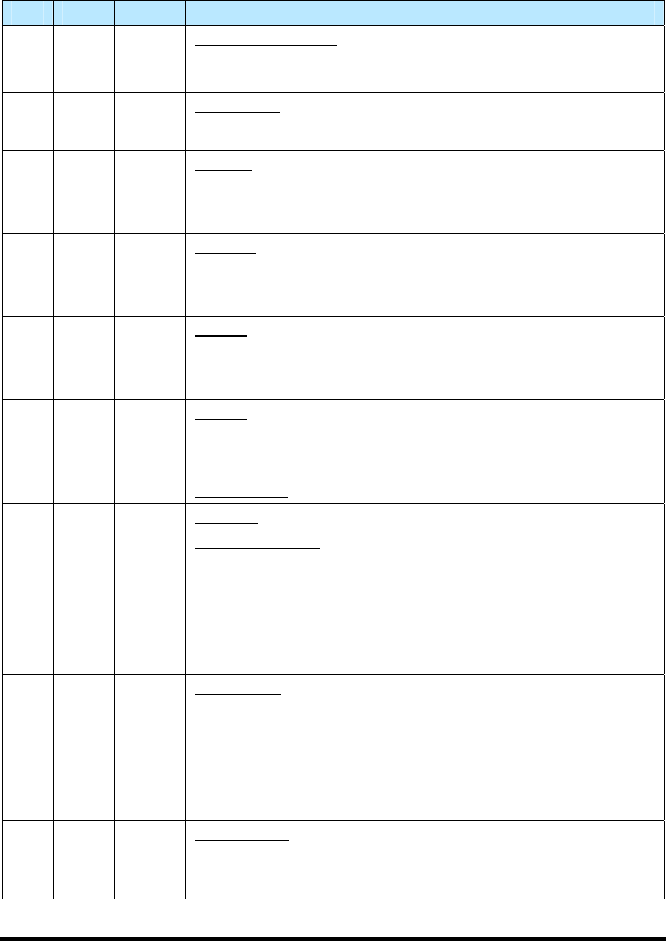
A-2 Appendix A – Data Dictionary Values
Table A-1 Data Dictionary Variables (continued)
VID Class Format Name and Description
9 EC U1 INITCONTROLSTATE. Initial (power-up) control super-state.
1 = Off-Line
2 = On-Line
10 EC U2 HEARTBEAT. The time in seconds that the Equipment will delay before
sending S1F1 to test the link. Units are seconds. Valid values are 0-3200
(a setting of zero will disable the heartbeat).
17 EC BOOL RPTYPE. This EC controls some aspects of the format of Event Reports
sent by this Equipment.
FALSE = Normal Event Reports
TRUE = Annotated Event Reports
18 EC U1 WBITS10. An EC which controls the W-Bit setting used when sending
S10F1.
0 = W-Bit not set
1 = W-Bit set
19 EC U1 WBITS5. An EC which controls the W-Bit setting used when sending
Alarm Reports (S5F1, S5F71, or S5F73).
0 = W-Bit not set
1 = W-Bit set
20 EC U1 WBITS6. An EC which controls the W-Bit setting used when sending
stream six messages (events, trace)
0 = W-Bit not set
1 = W-Bit set
21 SV U1 ABORTLEVEL. The AbortLevel of the most recent ABORT command.
22 SV U4 ALARMID. The ALID of the most recent Alarm transition.
23 SV List ALARMSENABLED. A list of all Alarms which are currently enabled.
Format as follows:
<L,n
1.<U4 ALID>
...
n.<U4 ALID>
>
24 SV List ALARMSSET. A list of all Alarms which are currently in the SET (on)
state. Format as follows:
<L
1.<U4 ALID>
...
n.<U4 ALID>
>
25 SV U1 ALARMSTATE. The Alarm State now in effect for the most recently
transitioned alarm.
0 = Alarm transitioned OFF
1 = Alarm transitioned ON