
Manual

System Configuration and Setup 4-39
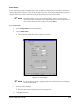
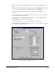
5. Click on Setup Light to identify the type of Light Source installed on your dispensing system.
!FmNT will automatically detect the type of Light Source. If not, contact Asymtek
Technical Support.
6. Select a
Graphics Level by clicking on the button next to the desired level.
7. Click on
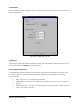
Setup Reticles to set up the parameters for your reticles.
!A Teach Window will prompt you through the process.
!Reticles are used to calculate size, measure distance, and center objects within the video
display screen.
- For example, when you are prompted to center the crosshairs over a dispensed dot,
reticles can help ensure that the crosshairs are as close to center as possible.
- Circle reticles are helpful during programming to ensure that the needle remains a safe
distance away from the part to avoid making contact, but also close enough to ensure
proper dispensing.
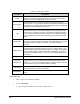
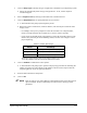
Table 4-9 Reticle Size Ranges
Reticle Size Range
Circles .005 in (0.127 mm) to video display size
Rectangle .005 in (0.127 mm) to video display size
Graduation Marks* .002 in (0.05 mm) to 0.1 in (2.54 mm)
*Graduation mark parameters determine the distance between each mark.
Every 5th graduation mark will be 20 percent taller than the others.
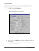
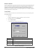
8. Click on Calibrate to calibrate the Vision System.
!A Teach Window will prompt you to perform a step-by-step procedure for calibrating the
number of pixels in the video display to the number of X and Y motor steps it takes the
Dispensing Head to travel the equivalent distance.
9. Enter the desired tolerances and options.
10. Click on OK.
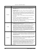
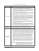
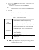
" NOTE Refer to Table 4-10 or Online Help for a detailed description of the Setup Vision
options available. Refer to Online Help for instructions on setting up reticle
parameters.