
Manual
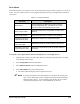

4-64 System Configuration and Setup
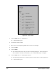
43. Click on Teach.
!The Dispensing Head moves to the Purge Station and purges, and then moves immediately
back to the sample substrate and dispenses a dot at each taught location. You are then
asked to align the Camera crosshairs with the dots.
44. Activate the
Enable Verification Step located in the bottom portion of the Teach Window,
and enter a tolerance value in the Verification Tolerance text box.
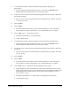
45. Use the Position Controls to center the Camera crosshairs over the first dot and click on
Teach. The Dispensing Head will skip to the next dot.
46. Repeat the previous step for all four dots. If using the Verification option, you will be asked
twice to verify Camera-to-dot alignment.
47. Click on
Done to accept the results.
!The Teach Window closes and you return to the Setup dialog box. Notice that the box
next to number 5 now has a check mark (9) in it to indicate that Step 5 is complete.
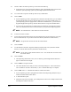
48. Click on
Run next to “6. Calculate the Camera-to-Height Sensor XY offset.”
!A Teach Window opens.
!If your system does not have a Height Sensor, this step will be grayed-out and inactive.
49. Choose an easily identifiable mark on the sample substrate, such as a dot or a line intersection,
and use the Position Controls to center the Height Sensor probe tip on the selected mark.
50. Click on
Teach.
51. Use the Position Controls to center the Camera crosshairs over the selected mark.
52. Click on
Teach.
53. Click on
Done to accept the results.
!The Teach Window closes and you return to the Setup dialog box. Notice that the box
next to number 6 now has a check mark (9) in it to indicate that Step 6 is complete.
54. If your dispensing system is equipped with a Dual-Action Dispensing Head, click on
Valve 2
in the Valve Offsets dialog box and perform the entire procedure again, except “1. Teach
Safe Z.”
55. When routine is complete, click
End in the Valve Offsets dialog box.