
Manual

System Configuration and Setup 4-57
11. Use the Position Controls to align the needle tip to the purge boot opening at the
Purge Station.
!If this procedure has been performed previously, you can click on
Go to XY and the
Dispensing Head will automatically move to the Purge Location.
12. Activate the Z-Axis controls and lower the Dispensing Head until the needle tip is flush with
the purge boot opening.
!Jog Z can be used to lower the needle deeper into the Purge Station, if desired. The range
is –0.2 inch to 0.2 inch.
13. Click on
Teach.
14. Click on
Done.
!The Teach Window closes and you return to the Setup dialog box. Notice that the box
next to number 2 now has a check mark (9) in it to indicate that Step 2 is complete.
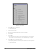
15. Click on
Run next to “3. Teach Scale Location.”
!The Dispensing Head moves to the Scale Station.
!A Teach Window opens.
16. Use the Position Controls to align the needle tip to the opening in the Scale Station lid.
!If this procedure has been performed previously, you can click on
Go to XY and the
Dispensing Head will automatically move to the Scale Location.
17. Activate the Z-Axis controls and lower the Dispensing Head until the needle tip is flush with
the opening.
!Jog Z can be used to lower the needle deeper into the Scale Station, if desired. The range
is –0.2 in to 0.2 in.
18. Click on
Teach.
19. Click on
Done.
!The Teach Window closes and you return to the Setup dialog box. Notice that the box
next to number 3 now has a check mark (9) in it to indicate that Step 3 is complete.
20. Click on
Run next to “4. Calculate the Needle-to-Height Sensor Z offset.”
!If your dispensing system is equipped with a single valve and no Height Sensor, this step
will be grayed-out and inactive. If your dispensing system is equipped with a Dual-Action
Dispensing Head and no Height Sensor, this step will be called "Calculate Z offset of
valve 2 relative to valve 1."
!The Dispensing Head moves to a safe Z height. The Height Sensor probe drops.
!A Teach Window opens.