
Manual

System Configuration and Setup 4-55
Valve Offsets
Valve Offsets allows you to perform one or all of the following setup procedures (Table 4-13) one step at
a time. The Valve Offsets routine can vary slightly depending on the type of Height Sensor installed on
your system.
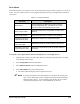
Table 4-13 Setup Procedures
Procedure Description
Teach Safe Z
The ideal height for the Dispensing Head as it travels
around the dispensing area. It should be set so that it
does not encounter any obstacles when it moves.
Teach Purge Location
Defines the location of the Purge Station in relation to the
needle tip.
Teach Scale Location Defines the Scale location in relation to the needle tip.
Calculate the Needle-to-
Height Sensor Z offset
Calibrates the needle to the Height Sensor probe.
Calculate the Needle-to-
Camera XY offset
Calibrates the needle XY location relative to the Camera.
Calculate the Camera-to-
Height Sensor XY offset
Calibrates the Height Sensor probe XY location relative to
the Camera.
To Perform a Valve Offsets Routine (RT Series Height Sensor or No Height Sensor):
1. Make sure the work area is clear of any obstacles so the Dispensing Head does not collide
with anything when it moves.
2. Select
Configuration from the Main Menu.
3. Select
Machine Offsets from the Configuration menu.
4. Select
Valve Offsets from the cascading menu.
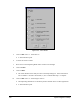
!The Valve Offsets dialog box shown in Figure 4-29 opens.
" NOTE In the upper left hand corner of the dialog box is an option for selecting your
valve. If your dispensing system is equipped with a Dual-Action Dispensing
Head, then select Valve 1. If your dispensing system does not have a Dual-
Action Dispensing Head, Valve 1 will automatically be selected.