
Instruction Manual


Programming Basics 7-11
Corner Fiducials
Corner Finder is an alternate method provided by the Asymtek Vision System to identify fiducials that
are part edges or lines or edge pairs, such as the edge of a die. In some cases accuracy is greatly improved
by identifying the corner of the part to be dispensed on as a fiducial.
The position of parts can be slightly rotated by automatic placement systems, or the parts can be
dislodged during the transfer process. By using pattern fiducials, you can ensure that the orientation of
the die is determined before dispensing.
The Corner Finder method assumes that edge images are a change in gray value from light to dark or
from dark to light. Edges are identified by locating these types of gray changes and analyzing them
statistically to see if they meet a given criterion. The programmer can set the search area just like with
Gray Scale. Corner Finder uses a vision tool called a Caliper designed to find edges or pairs of edges.
Selecting Good Edges
The same rules for size, uniqueness and contrast in selecting model fiducials applies to edges and
corners. Edges must be easily distinguishable from the background so that dark-to-light or light-to-dark
transitions are maximized. The Light Level and Gain settings can be adjusted to increase this contrast.
Edges should also be as “clean” and straight as possible, even though the software uses an averaging
algorithm.
Caliper Tool
The caliper tool has a caliper window overlay on the image of the edge as shown in Figure 7 -4. The tool
is strategically placed over the edges to be identified and can be sized in 2-dimensions. The
Search
Length
is the longer dimension of the caliper tool and crosses the edge to define the length of the area to
be searched for the gray transitions. It is important not to include more than one transition or edge along
this length. The
Projection Length is the shorter dimension, the distance that the application will
average gray-scale values down the edge in order to reduce noise and enhance the transition.
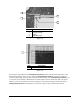
The calipers are applied perpendicular to the edges as shown in Figure 7 -5. The information obtained by
“averaging” the gray values of the pixels is calculated and the light-to-dark or dark-to-light transitions are
identified. The highest contrast transition within the caliper search area is considered to be the part edge,
so it is important that the highest contrast edge in the caliper search area be the part edge. Adjust the
Search Length, Projection Length and light levels until the most significant transition within the
caliper window is the edge of the part.