Fluidmove for Windows NT User Guide The part number for this manual is 195583, Revision A. The part number for the CD version of this manual is 195584. A clean room manual is also available upon request. To reorder this manual, please contact Asymtek, 1-760-431-1919.
Revision History Revision Date A 9/01 Description Initial Release. Changed from p/n 78-0009-00.
NOTICE All information contained in or disclosed by this document is considered proprietary by Asymtek. By accepting this material the recipient agrees that this material and the information contained therein are held in confidence and in trust and will not be used, reproduced in whole or in part, nor its contents revealed to others, except to meet the purpose for which it was delivered.
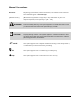
Manual Conventions Bold Text Dispensing system labels, buttons and switches, and software menu selections and commands appear in this text style. [Bracketed Text] [Bracketed Text] indicates a single key or key combination to press on a computer keyboard, such as [Enter] or [Alt + Tab]. WARNING! ? ii Personnel Safety Warning. This symbol appears in a shaded text block to warn you about actions that could cause personal injury or death. CAUTION! Property Damage Caution.
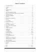
TABLE OF CONTENTS 1 GETTING STARTED..............................................................................................1-1 Overview ................................................................................................................1-1 Safety .....................................................................................................................1-1 2 INSTALLATION......................................................................................................
Circles ..................................................................................................................8-19 Area Fill Encapsulation .........................................................................................8-21 Placing Patterns ...................................................................................................8-24 9 ADVANCED PROGRAMMING ...............................................................................9-1 Overview ..............................
1 Getting Started Welcome to Fluidmove for Windows NT (FmNT). In most cases, FmNT should arrive already installed and configured for your dispensing system. If you should need to re-install FmNT, refer to the Installation section of this manual. Overview This manual is an instructional guide designed for system operators, computer programmers and process engineers. It provides a complete tour of the Fluidmove software with detailed explanations of all features.
2 Installation Overview In most cases, FmNT arrives already installed on and configured for your dispensing system from the Asymtek factory. The installation process is a typical Windows NT installation with user prompts. ? NOTE Refer to this section for a first time installation only. Upgraded versions of FmNT include their own installation instructions. The FmNT Installation Package The FmNT Installation Package contains, at a minimum, the following components.
Setting up the Dispensing System for FmNT Installation CAUTION! Please review the Safety section of the Operations Manual for your particular dispensing system before proceeding. Before you begin the installation procedure, make certain that your dispensing system is operational by following the checks below. ? NOTE Reference the dispensing system Operations Manual for the location of indicated components or options. 1.
Installation Procedure Most of the standard installation process is automated. You will be prompted to approve file locations and accept defaults. Automatic backups are made for some files during installation. Since FmNT is a true Windows software package, installing FmNT follows standard Windows installation procedures. CAUTION! This installation procedure should be performed by an application engineer, Information Systems manager or computer programmer.
3 Tour of Fluidmove Overview This chapter provides a tour of the unique Windows Graphic User Interface (GUI) of FmNT. Each window will be visited and explained in detail, along with all icons, toolbars and message areas. After reading this chapter, you will be ready to start the programming exercises. Estimated time to complete: 20 minutes System Setup and Operation To use FmNT, it is necessary to make sure that your dispensing system is in a known ready state.
Advanced Programming Menus The Programming Window is specifically designed to make programming intuitive and easy. The programmer is prompted through workpiece and fiducial setup. Logical tool bars and menu icons for common commands simplify keystrokes. In the Programming Window, the programmer has access to all machine controls, fluid control parameters and timing parameters, and can use them in the programming process.
User Interface You will find that the FmNT user interface was designed to utilize the simplicity and intuitiveness of Windows-based software. In this section, you will learn how to start FmNT and you will visit all of the major windows and menus within the FmNT environment. Starting FmNT The FmNT start-up procedure assumes that FmNT is already installed on your computer, and that the computer is turned ON and running Windows NT.
FmNT Windows and Menus Tour Use the mouse or trackball to explore FmNT while being guided on this tour of the menus. There are five major windows in FmNT: • Main Window • Tools Window • Programming Window • Production Window • Run Window A secondary window called the Teach Window, which displays the camera image from the vision system, is accessed from the Programming Window. Submenus and options are in drop-down menus below main buttons in all windows.
Figure 3-1 Tour of Fluidmove 3-5
Configuration Menu Click on Configuration in the Main Window to access the drop-down Configuration menu shown in Figure 3-2. This menu is used to configure program preferences, setup fluids, service stations and system components prior to starting a programming session. Menu items with an arrow next to them (") have secondary cascading menus listing additional features. All menu selections bring up dialog boxes for establishing configuration options.
The Setup Vision dialog box shown in Figure 3-3 opens. This dialog box allows you to identify and calibrate the vision system, and set specific preferences for fiducial searches. It also allows you to establish default vision parameter settings for creating new dispensing programs. Figure 3-3 Click on Cancel to exit the Vision Parameters dialog box.
Tools Window In the Main Window, click on Tools. The Tools Window shown in Figure 3-4 has buttons that allow direct communication with the major components of the dispensing system, the Dispenser, the Conveyors, the Scale and the Heaters. Figure 3-4 Click on Terminal to display the drop-down buttons shown in Figure 3-5.
Figure 3-5 Clicking on Dispenser, Conveyor 1 or Scale will bring up a Terminal Mode window. You can communicate directly with the selected device by typing commands in the Terminal Mode Window. Clicking on Heater opens the Heater Controls for configuring heater operation. For information on device commands, contact Asymtek Application Engineering. ? NOTE ? NOTE Dispensing systems equipped with dual-lane conveyors will have two conveyor buttons in this window, one for each conveyor.
Figure 3-6 Dispenser and Conveyor 1 shown in Figure 3-6, are used to access the I/O Test dialog box for testing the individual inputs and outputs for each device. ? NOTE Dispensing systems equipped with dual-lane conveyors will have two conveyor buttons in this window, one for each conveyor. Click on Dispenser to see the I/O Test dialog box. Choose Cancel and return to the Tools Window. Click on Jog to open the Jog Commands.
Jog Commands The Jog Commands, shown in Figure 3-7 are Position Controls for the dispensing head and the conveyors. These commands can be accessed from all major windows. To move the dispensing head forward, backward, left or right, click on one of the X-Y arrows. To move the dispensing head up or down, click on the Z arrows. To move rapidly in X, Y or Z, click on the double arrow buttons. To move the conveyor rail or belt, click on Conveyor 1, and then an arrow.
Programming Window The Programming Window is where all programming is performed. It has an extensive menu structure and many icons to simplify keystrokes. To view the Programming Window, click on Teach a Program in the Main Window. 1 4 2 5 3 6 Item 1 2 3 4 5 6 Description Menu Bar Process Toolbar Dispensing Program Command Insertion Point Program Name Pattern Name Text Box Program Commands Toolbar Figure 3-8 All of the icons and commands in this window are identified below.
Programming Window Menu Bar Each item on the menu bar activates a drop-down menu. Some drop-down menu selections open dialog boxes. The drop-down menu for each item and a brief explanation of each menu are shown below. Use the mouse or trackball to select one of the menu items to see the drop-down menu. Figure 3-9 The File menu contains all commands for opening existing programs, starting new ones and saving them. The Edit menu contains all commands for editing your dispensing programs.
Figure 3-10 The Setup menu contains all commands for preparing to create a dispensing program. The Run menu contains all commands for running and testing your dispensing programs. The View menu contains all commands for viewing log files, toolbars and status bars. The Help menu accesses Windows help. For FmNT help, click on the question mark on the Process Toolbar.
Process Toolbar The commands associated with each icon on the Process Toolbar are identified below. However, you will notice that FmNT toolbars have Tool Tips. As you move the cursor over a button, a “tip” appears below the button, explaining its function. If a button is greyed-out, that means that the command is not available at this point in the programming session. The Wet/Dry Run Mode and Video Display buttons toggle to change between the two modes.
Program Commands Toolbar The commands associated with each icon in the Program Commands Toolbar are identified below.
Dispensing Elements Toolbar An additional toolbar is available in the Teach Window. It is shown below.
Teach Window The Teach Window includes the Dispensing Elements Toolbar, a message area with instructions for the user, a camera video display of the dispensing area, command buttons for teaching locations, X-Y-Z Position Controls for moving the dispensing head, and a dialog box section that changes depending on the selected dispensing command. For example, the Teach Window that opens for programming a Weight-Control Line has a different dialog box than the Teach Window for programming an Area Fill.
2 1 3 4 6 5 7 Item 1 2 3 4 5 6 7 Description Instruction Message Box Teach Command Buttons Dispensing Elements Toolbar Video Display Dialog Box Area (varies depending upon dispensing element selected) X-Y-Z Position Controls Target Box Figure 3-15 Tour of Fluidmove 3-19
You can use the X-Y-Z Position Controls in the Teach Window, as shown in Figure 3-15, using a mouse or trackball. Or you can use the mouse or trackball to point and click on a location within the video display, or within the Target Box, to move the dispensing head around the dispensing area. To get used to using the Position Controls in FmNT, click on the WARNING! and then . The dispensing head will move approximately 50 mils to the right. Now, click on a location in the Target Box.
Production Window The Production Window is primarily used by operators during daily production runs. It is also used by process engineers while testing a new program. Load, Setup, Run and Shutdown have drop-down buttons and menus. Help accesses the Online Help. Jog opens the Jog Commands dialog box. Main takes you back to the Main Window. 1 Item 1 Description Name of Last Loaded Program Figure 3-16 To see the Load dialog box, click on Load. The File Open dialog box opens. See Figure 3-17.
1 Item 1 Description FmNT Program Files Figure 3-17 When you write a program in FmNT, the file is stored as a filename.fmw file on the hard drive of the computer or to a specified network drive. The last file saved is automatically loaded upon FmNT startup. Alternatively, other program files can be selected from the list as shown in Figure 3-17. Activating Attach Fluid File(s) attaches a fluid file, used to define the dispensing fluid characteristics, to the program you choose to run.
Figure 3-18 Most of the time, the operator will choose Setup Scripts to execute a setup routine and prepare for a production run. On-screen prompts cue the user for setup steps such as changing the needle or syringe. Customized, scripted setup routines can also be created. This will be demonstrated in a tutorial later in this manual. On some dispensing systems, if a non-scripted setup routine is selected, the Setup Scripts button will instead appear as a Prompted Setup button.
Figure 3-19 Clicking on Run Production leads to the Run Window. The list below Run Production contains options for testing a run before beginning production. This list will vary depending upon system configuration. Click on Run Production to access the Run Window.
Run Window This window contains system controls for starting, stopping or pausing the run and access to the SECS/GEM interface control, if the option is available. All fluid information entered from the Setup Fluid dialog box from the Configuration menu is shown in this window along with real-time fluid statistics such as a running timer of the pot life and thaw time since the beginning of the run. The Run Window shows the run statistics such as number of boards, cycle time and failure counts.
SECS/GEM Interface If you have the SECS/GEM Interface Option, refer to the SECS/GEM Interface section of this manual to tour the windows of the SECS/GEM Interface. For SECS/GEM Interface programming information, refer to the SECS/GEM Interface Option Reference Manual.
4 Heater Controls Overview The heater controls are used to setup and regulate the system heaters, needle heaters, fluid cooling and temperature sensing devices. This chapter explores the heater control user interface and teaches you how to set up the configurable options. Most settings are set at the Asymtek factory at the time of shipment and usually do not need to be changed.
This window is used as a quick-check for viewing Set Points (SP) and Present Value, also referred to as Process Variable (PV). Later in this chapter, you will learn how to set these options. Figure 4-1 Next, use the mouse or trackball to highlight loop one and double-click on the loop name.
Each loop has a dialog box which shows its settings under the Main tab. Figure 4-2 shows the Loop Parameters dialog box. On the Main tab, you set the temperature with Set Point (SP). The Output Value is the percentage of the total capacity of the heater being used to achieve or maintain the Set Point. Auto Mode regulates the loop temperature automatically. Manual Mode disables the automatic temperature controller and allows you to regulate loop temperature using the Output Value.
Figure 4-3 The Run Time tab, shown in Figure 4-3, shows the parameters for configuring heater behavior during production runs. The heaters can be turned off or turned down during fiducial searches. The heaters can also be turned off if the dispensing system does not receive a board or sits idle for a specified amount of time. Heater temperature can also be verified before dispensing begins. Select the Heat Control tab.
Figure 4-4 The Heat Control tab, shown in Figure 4-4, shows control parameters that are used to define the heating process for your specific system. All values in this dialog box should be set at the Asymtek factory prior to shipping and should not be changed by the user. For more information, consult the Anafaze User’s Guide. Next, select the Input tab.
Figure 4-5 The Input tab in Figure 4-5 is used to define the input types for each loop. Unused loops which do not have heaters attached are defined as “skipped”. Also, any process offsets to make up for signal inaccuracy are set here. All settings in this dialog box are set for each loop in your system at the Asymtek factory prior to shipping. Input Reading Offset can be used to make up for a calibration offset.
Figure 4-6 Figure 4-6 shows the Output tab which is used to define the type of output the controller uses for the heating process and specific parameters for the output type. All settings in this dialog box are set for each loop in your system at the Asymtek factory prior to shipping. The Type of output used most often for the dispensing system heaters is Time Proportioning (TP). In this Type, the percent output is converted to a percent duty cycle on the programmed cycle time.
Figure 4-7 The Alarm tab, shown in Figure 4-7, is used to setup the process alarms. An alarm can be set for each loop. The alarms notify the user of changes and deviations from the temperature Set Point. Process alarms can be set to notify the operator and/or control the output in the event of deviations from the Set Point. There are four alarm types: High Process, Low Process, High Deviation and Low Deviation. Figure 4-8 shows the activation and deactivation points.
Figure 4-8 Heater Controls 4-9
5 SECS/GEM Interface FmNT can be configured to interface with a GEM system. This is a factory-set option. Your dispensing system may not have a SECS/GEM interface option. If it does not, your SECS/GEM interface button in the FmNT Main Window will be grayed and disabled. Below is a description and tour of the user interface for the SECS/GEM option. It is intended as an Operator Guide.
2. Click on the Terminal tab and refer to Figure 5 -2. Figure 5 -2 > The Terminal tab is used to acknowledge and send messages to and from the host. 3. Click on the Setup tab and refer to Figure 5 -3.
> The Setup tab is used to setup the default Communication State, Control State, message and communication handling. Figure 5 -3 4. Click on the Communication tab and refer to Figure 5 -4.
> This tab is used to establish addresses for the host and the device. > Changes in this dialog box require exiting and restarting FmNT in order for the changes to take effect. Figure 5 -4 5. Click on Cancel to return to the Main Window. 6. In the Main Window, click on Run a Program. 7. In the Production Window, click on Run. 8. Click on Run Production to go to the Run Window. 9. Click on the SECS/GEM tab and refer to Figure 5 -5.
> This is the message area that the Operator has access to during a production run. Messages are acknowledged and received. Figure 5 -5 10. Click on Return to return to the Production Window. 11. Click on Main to return to the Main Window. This concludes the tour of the SECS/GEM interface user interface.
6 Setup and Configuration Overview This chapter guides you through basic configuration and setup routines. There are six types of setup and configuration routines in FmNT: • System Configuration • Preferences • Initial Setup • Prompted Setup • Programming Setup • Manual Setup System Configuration should be performed after initial installation, before beginning a programming session, and after making any hardware changes. Preferences can be changed at any time within FmNT.
System Configuration CAUTION! The System Configuration procedure should be performed by trained service personnel only. After installing your dispensing system, or after installing FmNT, it is necessary to identify certain options included on the system platform.
To configure the dispensing system: 1. Start FmNT. > Refer to “Starting FmNT” in the Tour of Fluidmove section in this manual for help. 2. In the Main Window, click on Configuration. 3. Select Machine Offsets from the Configuration menu. 4. Select Machine Offsets Parameters from the drop-down menu. > The Machine Offsets Parameters dialog box opens. See Figure 6-1. Figure 6-1 5. Click on the arrow next to the Sensor Type text box to view all available options. 6.
7. Click on OK. 8. In the Main Window, click on Configuration. 9. Select Setup Valves from the Configuration menu. > The Setup Valves dialog box opens. See Figure 6-2. Figure 6-2 10. If the type of valve installed on your dispensing system is not automatically highlighted in the Active Configuration box, use the mouse or trackball to select your valve from the list.
13. In the Main Window, click on Configuration. 14. Select Setup Height Sensor from the Configuration menu. > The Height Sensor Configuration dialog box opens. See Figure 6-3. Figure 6-3 15. Click on the arrow under Height Sensor Type and select the type of Height Sensor installed on your system. > If your dispensing system does not include a Height Sensor, select (none). > For X-1000 Series Dispensing Systems, click on CAN-HS to open the Height Sensor Configuration dialog box.
18. Select Setup Scale from the Configuration menu. > The Setup Scale Station dialog box opens. See Figure 6-4. Figure 6-4 19. Click on the arrow next to Type and select the type of Scale installed on your system. > If your dispensing system does not include a Scale, select (none). > If you select DI104, this dialog box will include a tab titled DI-104 containing additional configuration options. Refer to the Online Help for instructions. 20. Click on OK. 21. In the Main Window, click on Configuration.
Figure 6-5 23. Click on the arrow next to Vision System and select the type of Vision System installed on your dispensing system. > If you are not sure what type of Vision System is installed on your dispensing system, contact Asymtek Technical Support. 24. Click on the arrow next to Video Mixer and select the type of Video Mixer installed on your dispensing system. > If you are not sure what type of Video Mixer is installed on your dispensing system, contact Asymtek Technical Support. 25. Click on OK.
27. Select Setup Conveyors from the Configuration menu. > The Setup Conveyors dialog box opens. See Figure 6-6. Figure 6-6 28. Click on the arrow next to the Type box and select the type of conveyor installed on your system. > Most Century and Millennium Series Dispensing Systems use Automove to communicate with the conveyor. If you are using a non-Asymtek conveyor, select Custom. MPC555 is used on the X-1000 Series Dispensing System. Contact Asymtek for more information.
Figure 6-7 30. Click on the arrow under Style to view the entire list of conveyor types. ? > A brief description of each conveyor type appears below the Style box. NOTE The conveyor Style determines the name of the Conveyor Files used during operation. Refer to your system Operations Manual for more information. > Refer to the Online Help for explanations of each feature in this dialog box. 31. Click on OK.
34. Select Setup Heaters from the Configuration menu. > The Heater dialog box opens. See Figure 6-8. Figure 6-8 35. Click on the arrow next to the Heater (1 or 2) box and select the type of heater controller installed on your dispensing system. > Heater 1 refers to the left-most heater station. Heater 2 refers to the right-most heater station. Each heater station needs to be active in order for you to be able to configure it, and each heater station needs to be configured individually.
Preferences User Preferences for FmNT are located on the Configuration menu in the Main Window. The list below identifies the customizable preferences available. You may change these preferences at any time. Use (inches, mm or machine units) All measurements in FmNT will be displayed in your choice of units. Change Operator Level FmNT limits access to menus by use of this option. This option works in conjunction with Setup Password.
Passwords and Operator Level Passwords are used in conjunction with Operator Level to restrict access to certain windows and menu options within FmNT. Table 6-1 below shows the three levels of Operation and related levels of restriction. Table 6-1 Operator Levels of Restriction Operation Level Level of Restriction Service Highest level of operation. Allows full access to all menus and windows and all available features.
To see how the Operation Level restricts access to the menus, change the Operation Level as described below. Visit the menus and windows after changing. To change Operator Level: 1. Select Change Operation Level from the Configuration menu. 2. Select the level of operation you wish to access. 3. Type in the password for the Operator Level. > Refer to Table 6-2 for default passwords. > The menus will be appropriately restricted.
1 2 5 3 4 Item 1 2 3 4 5 Description System Components List of All Related Events for Selected System Component Enable All or Disable All Listed Events Activate to Log Time and/or Date of Event Scroll Bar Figure 6-9 6-14 Setup and Configuration
Initial Setup Initial Setup consists of establishing machine offset parameters.
Vision System Setup If the Vision System has not been calibrated since FmNT was initially installed, you will receive a notice when FmNT starts, indicating that the Vision System has not been calibrated. If the camera or any part of the vision system has been changed or upgraded, the Vision System will need to be re-calibrated. It is also a good troubleshooting routine to perform if you are having trouble identifying fiducials, corners or see an accuracy problem during dispensing.
3. Click on Calibrate in the Hardware segment of the dialog box. > A Teach Window opens. 4. Click on Next to load a board, if one is not already loaded. 5. Use the Position Controls to locate a Model Fiducial. 6. Click on Next. > FmNT captures an image of the fiducial and displays the image in the upper left-hand corner of the video display window. 7. Click on Next.
Figure 6-11 10. Click on Help for complete details on the reticles option. 11. Click on Done when complete. This concludes the tutorial on Vision Setup.
Calculate Master Offsets This screen-prompted routine identifies and records a Safe-Z Height for dispensing head travel, the XYZ locations of the purge and weigh stations, calibrates the camera-to-needle offset and the probe-to-needle offset. CMO also calibrates the camera crosshair to a known location. This routine is performed when the dispensing system is initially installed and configured. Those values and settings are recorded in FmNT.
Valve Offsets This screen-prompted routine identifies and records a Safe-Z Height for dispensing head travel, the XYZ locations of the Purge Station, Weigh Station and Needle. It also calibrates the camera-to-needle and needle-to-Height Sensor offsets. This routine is performed when the dispensing system is initially installed and configured. You can run this routine again at any time to insure dispensing accuracy or reflect hardware or software changes.
Scripted Valve Offsets Scripted Valve Offsets allows you to customize the machine offsets routine to fit your specific requirements. You can use one of the setup scripts included with FmNT, or create a custom script of your own. SVO also allows you to stop at any point in the setup process, and finish the process at a later time without having to start from the beginning. Refer to the Online Help for more information about creating your own Scripted Valve Offsets procedure.
Camera-Assisted Scripted Valve Offsets Camera-Assisted Scripted Valve Offsets is essentially the same as a regular Scripted Valve Offsets. However, SVO requires you to visually confirm needle placement. CASVO allows you to use the camera to visually confirm needle placement. Any existing SVO may be performed as a CASVO.
Changing Offsets Mode Changing Offsets Mode refers to changing from one Initial Setup routine to another. For example, follow the procedure below to change from Calculate Master Offsets to Valve Offsets. To change offsets mode: 1. In the Main Window, click on Configuration. 2. Select Machine Offsets from the Configuration menu. 3. Select Machine Offsets Parameters from the drop-down menu. > The Machine Offsets Parameters dialog box opens. See Figure 6-1. 4.
Prompted Setup Prompted Setup is generally the most frequently used setup procedure. It should be performed prior to all production runs, after changing the needle or valve, and if you are experiencing inaccurate dispensing. Part of Prompted Setup includes the Initial Setup procedure (whichever one is selected) as well as other system preparation tasks. Prompted Setup can also be performed as a Scripted Prompted Setup. Scripted Prompted Setup is described separately below.
3. Select Non-Scripted Setup Dialogs. 4. Click on OK. 5. In the Main Window, click on Run a Program. 6. In the Production Window, click on Setup. 7. Click on Prompted Setup. > A Teach Window opens. 8. Follow all on-screen prompts. > Refer to the Online Help for assistance. This concludes the tutorial on Prompted Setup. Scripted Prompted Setup Prompted Setup can be tailored into a Scripted Prompted Setup to meet your specific setup requirements.
Figure 6-13 8. Click on Prompted Setup. > Clicking on Syringe Change will launch a script specific to changing the fluid syringe. > The Prompted Setup dialog box, shown in Figure 6-14, opens. > The Task Description list will vary depending on your specific script.
9. Click on Run to End. 10. Follow all on-screen prompts. > Refer to the Online Help for assistance, if necessary. > Each step must be performed in the order that it is listed. > Scripted Prompted Setup is capable of running customized script files. Consult the Online Help for more information. ? NOTE If you have a Dual-Action or a Dual-Bracket dispensing head, the second valve must be selected and Scripted Prompted Setup must be run again. This concludes the tutorial on Scripted Prompted Setup.
Programming Setup Before you begin a programming session, it is recommended that you perform a Prompted Setup procedure. Also, before creating a dispensing program, you should visit the Configuration menu to setup your workpiece and fluid file, which is used to keep track of fluid characteristics and statistics. Fluid Files Fluid files record information about the dispensing fluids used in your programs.
To setup a fluid file: 1. In the Main Window, click on Configuration. 2. Select Setup Fluid Manager. > The Fluid Manager dialog box, shown in Figure 6-15, opens. Figure 6-15 3. Consult the Online Help for detailed instructions. This concludes the tutorial on fluid files.
Sample Programming Setup The following exercise will take you through a recommended programming setup. As you become more familiar with your system, you may want to modify this routine. This routine includes: • Loading a board • Creating a new file • Attaching a fluid file • Teaching Workpiece alignment • Teaching Workpiece fiducials ? You will need to have the Tutorial Board handy for this part of the exercise.
y-axis Dispensing System Workpiece y-axis Defined pojnts along Workpiece x-axis Workpiece x-axis Dispensing System Origin of Workpiece (0,0) Workpiece Angle Dispensing System Home Position Workpiece x-axis Figure 6-16 5. Click on Configuration. 6. From the Configuration menu, select Setup Fluid Manager to open the Fluid Manager dialog box, shown in Figure 6-15. 7. On the Purge Parameters tab, disable the Purge Maintenance feature by clicking on the box next to Enable Purge Maintenance.
14. Place the Tutorial Board as follows, depending on the type of dispensing system you have: A. For systems equipped with a conveyor, set the Tutorial Board (Side 1) at the mouth of the conveyor. Use the dispensing system Conveyor Controls or the Jog Commands in FmNT to set the proper width. Click on the Load Board icon. > The board is loaded into the dispensing area. The clamps should push the board up to the bottom of the rail slot. B.
26. Click on Next. > Teach the first fiducial in the same location where you taught the origin. > If the dot does not fit entirely inside of the square overlay in the video display, you will need to adjust the size of the Model Window. Notice the Model Size Width and Height text boxes in the area below the video display. 27. Click on the up arrows next to the Width and Height text boxes to adjust the size of the Model Window until the square is larger than the dot. 28. Click on Teach. 29. Click on Next.
39. Click on Teach. 40. Click on Done. > The Teach Window closes. 41. Click on File in the menu bar and select Save As. 42. In the File Name text box, type the name of the file. 43. Activate the Attach Fluid File(s) feature by clicking on it. > FmNT will attach the currently active fluid file, in this case, the fluid file you created earlier in this exercise, to the newly created program file. 44. Click on OK.
Manual Setup There are several manual setup procedures that you can perform at any time. These procedures are listed in the Production Setup list in the Production Window. You can tailor the contents of the Production Setup list to fit your particular setup requirements by clicking on Configuration in the Main Window, selecting Setup Script Options from the Configuration menu, and then clicking on Production Setup List. Consult the Online Help for more information. To view the Manual Setup options: 1.
7 Programming Basics Overview This chapter introduces the fundamentals of developing dispensing programs in FmNT. These skills prepare you for more complex programming in the next two chapters. It is essential to be familiar with the tools you will use to program, such as the Vision System software. This chapter explains the use of Model Fiducial Finder and Corner Finder in the Vision System. You will be taught basic tips on how to define and recognize good fiducials and how to set up for edge detection.
Building a Program in FmNT It is important to learn how to build programs in FmNT. Complex multipass dispensing programs are built by first defining patterns, then adding those patterns to the whole workpiece. When building programs, it is important to keep in mind that you want to develop the fastest method of dispensing in order to maximize production throughput. You gain this efficiency by constructing the patterns and adding them to the program in the most time-effective manner.
Look at the following program instructions in Figure 7 -1. Specific pattern program lines are displayed separately. Only the instructions for the currently selected pattern are displayed in the programming screen. The currently selected pattern is indicated in the Pattern Name text box. As shown, the currently selected pattern is Workpiece. The instructions for Workpiece shown in the programming screen are function calls to a sub-pattern called “chip 1.
The Vision System An essential component of the programming and production process of fluid dispensing is the Vision System. The Vision System is capable of automatically locating features on the workpiece so that patterns can be placed accurately. The Vision System hardware consists of a camera, light source, vision processor board and video mixer board.
Fiducial Detection The Vision System has three tools or methods to find fiducials as described below. The exercises that follow will teach you how to use these tools. The first exercise will use the Model Finder method to define Workpiece fiducials. The second exercise will use the Corner Finder method to define a pattern fiducial. Defining Workpiece and pattern fiducials is the crucial first step to creating accurate dispensing programs.
Table 7 -1 Fiducial Ratings Shape Characteristics £ donut Excellent. Immune to rotation. Inner and outer diameters allow for further definition. # pound Good. Uniqueness maintained under rotations. l circle Good. Immune to rotations. ❍ hole/gap Poor. Requires machining accuracy to match definition. Not repeatable between different workpieces. : cross Poor. Single axis identification does not allow for poor quality printing of the shape.
1 3 2 4 5 6 7 Item 1 2 3 4 5 6 7 Description Search Window Model Window Metal Dot Fiducial Outer Contrast Ring Metal Dot Fiducial on Dark Background Donut Fiducial with High Contrast Background Shaped Fiducial Pattern Figure 7 -3 Programming Basics 7-7
To teach a model fiducial: 1. In the Main Window, click on Teach a Program. 2. Load the Tutorial Board (Side 1) as follows, depending on the type of material handling option your system has: A. For systems equipped with conveyors, set the Tutorial Board (Side 1) at the mouth of the conveyor. Use the dispensing system Conveyor Controls to set the proper width. Choose Manual Load Board from the Setup menu or click on the Load Board icon. > The board will be loaded into the dispensing area.
14. Using the Position Controls, move the dispensing head to the lower left-hand corner (LLHC) of the tutorial board and center the crosshairs on the dot in the LLHC. 15. Click on Teach. 16. Click on Done. > Now you are asked to select the method for defining the first fiducial. > Notice the choices for fiducial finding offered below the video display window. 17. Select the Model Finder method. 18. Click on Next. > Notice the smaller white-lined box in the video display window.
23. Click on the Run Time tab. > Check for location tolerances means that FmNT will check the found location of the fiducial and compare it to the location where it expected to find it. If the difference between the two locations is greater than the Location Tolerance, FmNT will consider the fiducial to be “Not Found.” This ensures that an incorrect fiducial or other feature is not considered to be a correct fiducial, and prevents dispensing on parts that are too far away from their expected locations.
Corner Fiducials Corner Finder is an alternate method provided by the Asymtek Vision System to identify fiducials that are part edges or lines or edge pairs, such as the edge of a die. In some cases accuracy is greatly improved by identifying the corner of the part to be dispensed on as a fiducial. The position of parts can be slightly rotated by automatic placement systems, or the parts can be dislodged during the transfer process.
1 2 3 4 Item 1 2 3 4 Description Search Length Projection Length Caliper Application Point Figure 7 -4 1 Item 1 Description Multiple Calipers Figure 7 -5 When using a single fiducial with Orthogonality Tolerance, FmNT calculates the angle of the corner defined by the calipers. If the corner is within the Orthogonality Tolerance, the part is considered square and dispensing on the part will be performed.
? NOTE You should first perform the preceding tutorial on Model Fiducials before performing the following exercise. To use Corner Finder to locate an edge: 1. In the Programming Window, click on Pattern on the Program Commands toolbar. 2. Select Create Pattern. > The Create Pattern dialog box opens. 3. Type Sample in the text box and choose One fiducial. 4. Click on OK. > A Teach Window opens asking you to “Teach pattern origin.” 5.
13. Adjust the Search Length and Projection Length to experiment with their effect. TIP The Search Length should be optimized so that it contains only one gray value transition (light to dark, or dark to light). A longer caliper increases the range for finding the corner, but also increases the chance of finding the wrong corner. TIP Projection Length controls the averaging for the transition amplification. A wider caliper is better for rough edges or eliminating noise caused by traces on the board.
Editing Fiducials You can edit fiducials defined for your workpiece at any time. You may want to edit fiducials if the system fails to find too many of them during production runs. The procedure below is a reference procedure and does not need to be performed now. To edit fiducials: Using Model Finder 1. Load the workpiece board. 2. In the Programming Window, make sure that the name of the pattern containing the fiducials you wish to edit appears in the Pattern Name text box.
8 Beginning Programming Overview This chapter introduces you to the fundamental dispensing commands and patterns that form the foundation of all dispensing applications. You will learn how to create basic dispensing patterns. Later in this chapter, you will learn how to place those patterns at multiple locations on the same workpiece. It is essential for you to develop the basic programming skills in this chapter. These skills will be further developed in the next chapter, “Advanced Programming”.
Lines Lines are a common dispensing element for flip chip underfill applications. Weight control lines, which are lines whose fluid weight can be user-defined, are often used in underfill applications. In this exercise, you will learn how to program and dispense simple lines. Afterwards you will learn how to edit the lines. Weight control lines are treated separately in the next section. Estimated time to complete: 45 minutes.
11. Click on Teach. 12. Use the Position Controls to move the crosshairs to the endpoint of the line. 13. Click on Teach. 14. Click on Done. > In the Program Window, you should see the following: 1 LINE: 1, Start: (X1,Y1), End: (X2,Y2) 2 END: > X1,Y1 are the coordinates for the starting point of the line. X2,Y2 are the coordinates for the end point of the line. 15. Repeat Steps 8 through 14 to program the next two lines below the first line on the Tutorial Board.
Editing the Lines If you were not satisfied with the lines dispensed, you can simply edit them. This exercise will teach you how to edit existing lines in a program. For this exercise, you will shift the lines over and shorten them. To edit the lines (shift them over and shorten): 1. From the Edit menu in the Programming Window, select Edit Pattern. 2. Click on Workpiece. > The dispensing head will move after your response. 3. Place the cursor on 1 LINE in the program and double-click.
Weight Control Lines Most lines for flip chip underfill applications are weight control lines. These are lines where the programmer can customize certain line parameters for greater control over specific characteristics of the line. A defined amount (weight) of fluid is dispensed over a defined length of line or pattern. Estimated time to complete: 45 minutes. To view the customizable parameters for weight control lines: 1. In the Programming Window, click on Edit and select Edit Line Parameters.
Pre-Move Delay Factor Some fluids have a high viscosity which means that they do not dispense as quickly as lower viscosity fluids. The Pre-Move Delay Factor increases the time that the dispensing head is parked with the valve ON, prior to a programmed move. The delay at the beginning position insures that a full line is dispensed. The units are seconds. Typically, 50 ms (0.050 sec) is sufficient for most underfill fluids. Down Speed The Down Speed is how fast the dispensing head lowers to dispense.
Backtrack Length This is the horizontal distance that the dispensing head moves back over the dispensed line after raising up the Backtrack Gap distance. This encourages congealed fluids to detach and distributes any excess fluid back across the line. The units are inches. Typically, 30 - 40 mils (0.030 - 0.040 in) is sufficient. Backtrack Speed This is the speed that the dispensing head travels when moving along the Backtrack Length. The units are inches/second. Typically, 2 in/sec is sufficient.
To program weight control lines: 1. Perform the Programming Setup procedure in the Setup and Configuration section of this manual, then return here. > Load Side 1 of the Tutorial Board. > When you create the Workpiece, define the Workpiece Alignment. > Choose No Fiducials. 2. Click on Dispensing Elements on the Program Commands toolbar. > A Teach Window opens. 3. Click on Weight Control Lines.
4. Type 20 mg in the Total Weight text box. > Entering 20 mg means that 20 mg of fluid will be dispensed along the length of the line you will now define. 5. Move the camera crosshairs to the beginning of the top Basic Line on Side 1 of the Tutorial Board. 6. Click on Teach. 7. Move the camera crosshairs to the end of the line. 8. Click on Teach. 9. Click on Done. > A message box opens, indicating the calculated line speed for the newly created weight control line. 10. Click on OK.
23. Click on Done. > A message box opens, indicating the calculated line speed for the newly created weight control line. 24. Click on OK. 25. In the Programming Window, select Edit Line Parameters from the Edit menu to open the Line Parameters dialog box. 26. Set the Line Parameters for Line Type 1 to: Pre-Move Delay Factor: 0.1 Down Speed: 2 Down Acceleration: 300 Dispense Gap: 0.015 Speed: (not used for weight control lines) Shut-off Distance: 0.010 Suckback: 0.000 Dwell: 0.0 Backtrack Gap: 0.
Dots FmNT can dispense precision dots as well as lines. Dots are used in surface mount adhesive (SMA) applications. For this exercise, use the valve conditioning fluid. The conditioning fluid more closely simulates the characteristics of SMA fluids. The size of the dots and characteristics of the dispensing are controlled by Dot Parameters in the Edit Dot Parameters. You will learn how to program and dispense dots on the workpiece.
Valve-On Time This parameter controls the time the valve is on while positioned over the dispensing location. The time interval affects dot size. The longer the Valve-On Time, the larger the dot. The units are in seconds. The typical value is 30 ms. However, the Valve-On time can be as long as 6 seconds, depending on the desired dot size and fluid properties. Dispense Gap The Dispense Gap is the distance between the substrate you are dispensing on and the needle tip during dispensing.
Suckback At the end of dispensing a line or a dot, the valve is reversed for the Suckback period to remove any material from the tip of the needle. The Suckback value should be set according to fluid viscosity. Generally, 10 ms (0.010 sec) is sufficient. Mid-Move 1 and Mid-Move 2 These parameters are advanced dot parameters used for special applications and testing. For more information, contact Asymtek Application Engineering.
To program dots: 1. Perform the Programming Setup procedure in the Setup and Configuration section of this manual, then return here. > Load Side 1 of the Tutorial Board. > When you create the Workpiece, define the Workpiece Alignment. > Choose No Fiducials. 2. Click on Dispensing Elements from the Program Commands toolbar. 3. Select Dot from the Dispensing Elements toolbar. 4.
15. Set the Dot Parameter Valve-On Time to 0.250 sec, and Dwell Time to 0.050 sec. Set all the other parameters for Type 2 to the same settings established for Type 1. > This will adjust the Valve-On Time and Dwell Time for Type 2 dots. 16. Click on Apply. 17. Click on OK. 18. Select Dry Run from the Run menu. > The dispensing head will move after your response. > Watch to see the camera locate the position of the dots. 19. Select Wet Run from the Run menu. > Watch to see the dots dispensed.
Arcs There are two available methods for teaching an arc: • Start, Middle, End (S,M,E) • Center The S,M,E method asks you to teach a starting point for your arc, a middle point, and an end point. The three points are treated like a part of a circle and the arc will be dispensed along the three points accordingly. The Center method asks you to teach a starting point on the arc followed by a center point.
Figure 8-4 Beginning Programming 8-17
To program an arc: 1. Perform the Programming Setup procedure in the Setup and Configuration section of this manual, then return here. > Load Side 1 of the Tutorial Board. > When you create the Workpiece, define the Workpiece Alignment. > Choose No Fiducials. 2. Click on Dispensing Elements from the Program Commands toolbar. 3. Click on Arc on the Dispensing Elements toolbar. 4. Select the method (S,M,E or Center) for teaching the arc. 5.
Circles There are two available methods for teaching a circle: • Start, Middle, End (S,M,E) • Center The S,M,E method asks you to teach a starting point for your circle, a middle point, and an end point. The three points are defined as points along the circumference of the circle and the circle will be dispensed along the three points accordingly. The Start and End points may be the same point, but it is not necessary to program the circle in that manner.
10. Click on Teach. 11. Click on Done. 12. In the Programming Window, select Dry Run from the Run menu. > The dispensing head will move after your response. > Watch to see the camera trace the path of the circle. 13. Select Wet Run from the Run menu. > Watch as the circle is dispensed. > Examine the board for quality and accuracy. This concludes the tutorial on Circles.
Area Fill Encapsulation Area Fill dispensing is used to encapsulate a part on a board. It is important for the fluid to cover the part completely without voids. The process by which the fluid is dispensed should be fine-tuned for best results. Area Fills can also be dispensed using Weight Control. In that case, a defined weight of fluid is dispensed in the Area Fill. If Weight Control is not used, the Line Parameters for the selected Line Type are used.
10. Select Dry Run from the Run menu. > The dispensing head will move after your response. > Watch to see the camera move across the rectangular pattern. Help If you get an error message that the speed is too slow, re-check your dot parameters and try again. 11. Select Wet Run from the Run menu. > Watch as the Area Fill dispenses. > Examine the board for quality and accuracy.
1 2 3 Item 1 2 3 Description Corner 1 Spacing between Lines Corner 2 Figure 8-6 This concludes the tutorial on Area Fill.
Placing Patterns Patterns, as explained in “Building a Program” earlier in this chapter, are essential building blocks of complex dispensing programs for workpieces. In this exercise you will learn how to create a simple dispensing pattern and place it on a workpiece at multiple locations. For this exercise, you will create a simple L-shaped underfill pattern and place it on the workpiece Tutorial Board. You will perform a wet dispense.
4. Select One fiducial. > Skip Marks are basically specialized fiducials and will be explained later in the Advanced Programming section of this manual. 5. Click on OK. > A Teach Window opens asking you to teach the pattern origin. 6. Use the Position Controls to center the camera crosshairs on the dot nearest the ULHC of the first square in the top row on Side 2 of the Tutorial Board. > This will be the Origin of the pattern. 7. Click on Teach. 8. Click on Done.
19. Enter 20 mg in the weight text box and choose Style 1. 20. Use the Position Controls to center the crosshairs on the ULHC of the first square in the top row on Side 2 of the Tutorial Board. 21. Click on Teach. 22. Use the Position Controls to center the crosshairs on the URHC of the same square. 23. Click on Teach. 24. Use the Position Controls to center the crosshairs on the LRHC of the same square. 25. Click on Teach. 26. Click on Done.
39. Select Dry Run from the Run menu. > Watch to make sure that the program goes through the following steps: • Locate Fiducials 1 (ULHC) and 2 (LRHC) of the Workpiece. • Locate Fiducials for each of the squares along the top row. • Dry dispense L-shaped line around each square. 40. Select Wet Run from the Run menu. > Watch as the pattern is dispensed in both locations. > Examine the board for quality and accuracy. This concludes the tutorial on Placing Patterns.
9 Advanced Programming Overview This chapter discusses and demonstrates some of the more advanced techniques for perfecting your dispensing programs. You will perform two underfill tutorials, one L-shaped pattern and one U-shaped pattern. You will learn how to increase throughput by using timers and skip marks and reusing fiducials and height sense information. ? NOTE You should complete the preceding chapter, Beginning Programming, before attempting the tutorials in this chapter.
Skip and Prompt can be used for production runs. Occasionally chips are placed skewed on a workpiece or a defect interferes with a fiducial. In this case, if Skip is chosen, the program will automatically skip the fiducial or part it is searching for and continue with the next step in the program. If Prompt is selected, the Operator is asked to either re-teach the unfound location, or skip it and continue the run.
1 2 4 3 Item 1 2 3 4 Description Needle Tip ½ Needle Diameter + 7 mils from Corner in X and Y-axes Chip Chip Offset Perimeter Figure 9-1 Advanced Programming 9-3
Underfill Patterns There are several types of line patterns used for underfill applications. Two common types are L-shaped and U-shaped patterns as shown in Figure 9-2. Variations of these types of underfill patterns are used as well. These patterns and processes are designed to assure complete underfilling without excess and to prevent voids in the underfill.
Advanced Underfill Workpiece In these exercises, you will learn how to program an entire underfill workpiece. The first exercise will be the L-shaped pattern. The second exercise will be the U-shaped multipass pattern. You will learn when to insert timer commands, height sense commands, flow rate measurements, use skip marks and re-use fiducials. Estimated time to complete: 60 minutes For the exercise below, you will use Side 2 of the Tutorial Board.
To program the workpiece with L-shaped underfill patterns: 1. Perform a Programming Setup. (See the Setup and Configuration section of this manual.) > Load the Tutorial Board to Side 2. > Choose Two Fiducials, and Learn Workpiece Angle first. > For your fiducials, use the Model Finder method and program Fid 1 as the fiducial in the lower left-hand corner (LLHC) and Fid 2 as the fiducial in the upper right-hand corner (URHC) on Side 2 of the Tutorial Board. 2.
17. Test Fid 1 or click on Next. > The Teach Window closes and the Edit Pattern Skip Info dialog box opens. 18. Select Skip Pattern If Mark Not Found. 19. Click on Teach Skip Mark. > A Teach Window opens asking you to select the method for teaching your skip mark. 20. Select Model Finder. 21. Click on Next. 22. Use the Position Controls to center the camera crosshairs on the dot slightly above and to the left of where you taught the origin and fiducial. 23. Click on Teach. 24.
32. Click on OK. > Notice the program lines: 1 START PASS: FOR PASS 1 2 END PASS: 3 START PASS: FOR PASS 2 4 END PASS: 5 END 33. Place the cursor on the first END PASS. 34. From the Program Commands toolbar, click on Dispensing Elements. > A Teach Window opens. 35. From the Dispensing Elements toolbar, click on Find Substrate Height. 36. Use the Position controls to move the dispensing head to a location near the flip chip model.
46. Click on Done. > A message box opens indicating the calculated line speed. 47. Click on OK. 48. From the Program Commands toolbar, click on Time and select Reset Multipass Timer. > This will start the timer after the first line is dispensed. 49. Place the cursor on the second END PASS and click on Time in the Program Commands toolbar. 50. Select Await Multipass Timer. > The Await Multipass Timer instruction dialog box opens. 51. Type in 10 seconds.
64. From the File menu, select Save and type in undrfil.fmw to save your program as undrfil.fmw. > Your program should look like this: 1 START PASS: FOR PASS 1 2 FIND SUBSTRATE HEIGHT: (x, y) 3 WEIGHT CONTROL:50.00, 1, ([x1, y1],[x2, y2], [x3, y3]) 4 RESET MULTIPASS TIMER: 5 END PASS: 6 START PASS: FOR PASS 2 7 AWAIT MULTIPASS TIMER: 10 seconds(s) 8 WEIGHT CONTROL:30.000,1, ([x1, y1],[x2, y2], [x3, y3]) 9 END PASS: 10 END 65. In the Pattern Name text box, select Workpiece.
78. Use the Position Controls to move the dispensing head to the ULHC of the first flip chip model in the top row of flip chip models. 79. Click on Teach. 80. Click on Done. > You program will look like this: 1 MEASURE FLOW RATE 2 LOOP PASS: FROM 1 TO 2 3 DO MULTIPASS: Lfill AT (x1, y1) 4 NEXT LOOP: 5 END: 81. Place the cursor on NEXT LOOP. 82. Click on Pattern on the Dispensing Process toolbar. 83. Select Place Multipass Pattern. 84. In the Teach Window, select Lfill in the Available Patterns text box.
92. Select Check Children If Mark Not Found. > This means that if the Workpiece skip mark is not found, the Lfill skip marks will be checked. 93. Click on Teach Skip Mark. > A Teach Window opens asking you to select the method for teaching the skip mark. 94. Select Model Finder. 95. Click on Next. 96. Use the Position Controls to center the camera crosshairs on the dot in the ULHC of the Tutorial Board. > This will be the Workpiece skip mark. 97. Click on Teach. 98.
112. From the Run menu, select Wet Run. > ? Watch to make sure that the program, performs the following: • Finds two corner fiducials on the workpiece. • Finds the Workpiece skip mark. • Finds the fiducials at each flip chip model location for the Lfill pattern. • Finds the Lfill skip marks. NOTE The skip mark for the second flip chip model should not be found and the pattern should be skipped. • Performs a Flow Rate measurement. (Only performed on Wet Run.
To program a U-shaped multipass: 1. Perform a Programming Setup. (See the Setup and Configuration section of this manual.) > Load the Tutorial Board to Side 2. > Choose Two Fiducials, and Learn Workpiece Angle first. > When prompted to teach your fiducials, program Fid 1 as the fiducial in the ULHC and Fid 2 as the fiducial in the LRHC of Side 2 of the Tutorial Board. 2. From the Main Window, click on Teach a Program. 3. From the Program Commands toolbar, click on Pattern and select Create Pattern. 4.
16. Click on Teach. 17. Test the fiducial or click on Next. 18. Click on Done. > A message box opens indicating that the dispensing head is about to move to the “Workpiece” origin. > The dispensing head will move after your response. 19. Click on OK. 20. Select U-pass from the Pattern Name text box. > A message box opens indicating that the dispensing head is about to move to the “U-pass” origin. > The dispensing head will move after your response. 21. Click on OK. 22.
28. Click on Teach. > The program should look like this: 1 START PASS: FOR PASS 1 2 FIND SUBSTRATE HEIGHT: (x, y) 3 END PASS: 4 START PASS: FOR PASS 2 5 END PASS: 6 START PASS: FOR PASS 3 7 END PASS: 6 END 29. From the Program Commands toolbar, click on Dispensing Elements. 30. Click on Weight Control Lines. 31. Enter 30 mg in the Total Weight text box and select Line Style 1. 32.
45. Enter 30 mg in the Total Weight text box and select Line Style 1. 46. Use the Position Controls to move the dispensing head to the ULHC of the first flip chip model in the second row of flips chip models. > Use Chip Offset or reticles. 47. Click on Teach. 48. Use the Position Controls to move the dispensing head to the URHC of the same flip chip. > Use Chip Offset or reticles. 49. Click on Teach. 50. Click on Done. 51. From the Program Commands toolbar, click on Time. 52.
64. Click on Teach. 65. Use the Position Controls to move the dispensing head to the URHC of the same flip chip. > Use Chip Offset or reticles. 66. Click on Teach. 67. Click on Done. 68. From the File menu, select Save As and type in multipas.fmw to save the file as multipas.fmw. > Your program should look like this: 1 START PASS: FOR PASS 1 2 FIND SUBSTRATE HEIGHT:(x, y) 3 WEIGHT CONTROL:30.
74. Select Loop Block and type in 3 for the three passes (U-shaped line and two seal passes) in U-pass. 75. Place the cursor at Next Loop. 76. Click on Pattern on the Program Commands toolbar, and select Place Pattern. 77. In the Teach Window, select U-pass in the Available Patterns text box. 78. Use the Position Controls to center the camera crosshairs on the ULHC of the first flip chip model in the second row of flip chip models. 79. Click on Teach. 80. Choose Done.
88. From the File menu, select Save. 89. From the Run menu, select Dry Run. > Make certain that the program executes the following steps correctly: • Finds two corner fiducials on the workpiece. • Finds the fiducials at each flip chip model location for the U-pass pattern. • Perform a Flow Rate measurement. (Only performed on Wet Run.) • Performs a substrate height measurement. • Dry dispenses two lines around each of the flip chip models.
10 Running Production Overview After a program has been built and the dispensing process perfected, the program will be used in a Production Run. This chapter will guide the Operator through a System Set-up, Production Run and Shut Down. The exercises in this chapter assume that the dispensing system is in good working order as described in “System Setup and Operation” in the Tour of Fluidmove section of this manual.
8. After the file has loaded, click on Run in the Production Window. 9. Click on Run Production. > The Run Window opens. See Figure 10-1. > A message box appears requesting you to “Clear the conveyor”. 10. Clear the conveyor. > Click on Jog to access the conveyor controls, if necessary. 11. Click on OK. 12. Place a Tutorial Board at the mouth of the conveyor. 13. Click on Go. > The message “Waiting for a board” will appear. > The Tutorial Board will be conveyed into the dispensing area.
To Simulate a Production Run This exercise will teach you how to simulate a production run on conveyorized dispensing systems. Follow the procedure below to simulate a production run. To simulate a production run: 1. Unload all boards. 2. Shutdown the dispensing system. > Refer to the system Operations Manual for shutdown instructions, if necessary. 3. Install the TS-01 as indicated below: a. Attach the TS-01 Upstream/Downstream cable adapter to the TS-01 box. b.
14. Clear the conveyor. 15. Click on OK. 16. Click on Go. > The message “Waiting for a board” will appear. 17. Place a Tutorial Board at the mouth of the conveyor. 18. Press the #3 TS-01 button to move the board to the dispensing station. > Dispensing will be performed. > When dispensing is complete, the red LED #4 on the TS-01 turns ON. 19. Press the #5 TS-01 button. > The board will either stop at the post-dispense zone, if there is one, or exit the machine entirely if there is not.
Shutdown To shutdown a Production Run at any time, use the Run Control Buttons in the lower right corner of the Run Window. See Figure 10-1. The Shutdown button in the Production Window does not shut down the dispensing system. It allows the operator to perform a valve cleaning procedure or unload a board. To shutdown the dispensing system, refer to the Startup\Shutdown section of the system Operations Manual.
Glossary area-fill: Dispensing lines of fluid within a geometric pattern to completely cover an area. crosshairs: Two lines intersecting at a 90° angle in the center of the video display on the computer monitor. auer boat: A metal material handling plate used to transport parts into automated systems. dispense head: The dispense head is what moves during dispensing operation. The valve, height sensor and similar options attach to the dispense head.
flow rate: The amount of fluid in milligrams per second that is flowing from the valve. gantry: A non-conveyorized dispensing area on a non-conveyorized dispensing system. heaters: Either contact or infrared modules located between the conveyor rails or inside of the tooling plate (in the pre-dispense, dispense and post dispense areas of the dispensing system). Used to heat parts during dispensing and control the cure of the epoxy.
Notepad: A Microsoft Windows accessory software application that can be used to read .TXT files, such as the SPC files compiled during Event Logging. offset camera: Camera that uses crosshairs in the Vision System to locate XYZ locations. operator: A person running preprogrammed dispensing systems and performs routine maintenance. outputs: Electrical signals to control devices that must turn On and Off on command. pattern: A command or set of commands that use fiducials for dispensing lines, dots, etc.
skew correction: The ability of the software to adapt to a part not oriented correctly on the workpiece. underfill: The process of flowing epoxy underneath a flip chip on a PCB to completely seal the solder bumps. SMEMA: Surface Mount Equipment Manufacturers Association. URHC: Upper Right Hand Corner. statistical process control (SPC): Machine performance data gathered and stored in text files. You can review SPC files to monitor system performance.
Index –A– alarms, 4-8 Anafaze, 4-1 area fill, 8-21 Asymtek Vision for Windows (AVW), 3-2 automatic back-ups, 2-3 –B– backtrack gap, 8-6 backtrack length, 8-7 –C– calibration, 3-1 camera, 6-16 caliper tool, 7-11 calipers density, 7-13 sizing, 7-13 camera calibration, 6-15 on/off, 3-15 video overlay, 3-2, 3-18 camera-offset, 3-1 chip offset, 6-17, 9-2 chip tolerance, 3-1 commands, 3-13, 3-15, 3-16, 3-17, 7-1 configuration, 3-4, 6-1, 6-15 configuration menu, 3-6 conveyor, 6-1 conveyor controls, 3-11 cooling
–I– I/O, 3-10 I/O testing, 3-10 initialization, 3-1 installation, 1-1, 6-1, 6-15, 6-19, 6-20, 6-21, 6-22 Installation Package Installation Guide, 2-1 Tutorial Board, 2-2 User Guide and Tutorial, 2-1 –J– jog commands, 3-10, 3-11 –L– light levels, 3-1, 7-11 light source, 7-4 lines, 8-2 parameters, 8-10 weight control, 8-5, 9-2 –M– Main Window, 3-4, 3-5, 3-6 master offsets, 6-19, 6-20, 6-21, 6-22 measurements, 6-11 menu bar, 3-13, 3-14 menu commands, 3-13 menu restrictions, 6-13 mid-move 1 and mid-move 2, 8
–T– Teach Window, 3-4, 3-18, 3-19 temperature, 4-2 terminal communication, 3-9 terminal mode, 3-8, 3-9 thaw time, 3-25 timers, 9-1, 9-5 tool tips, 3-15 Tools Window, 3-4, 3-8, 3-9, 3-10 TS-01 Interface Simulator, 10-1 tutorial boards, 1-1, 7-3 –U– underfill patterns, 9-4 –V– valve-on time, 8-12 valves changes to, 6-19, 6-20, 6-21, 6-22 control, 8-6, 8-12 vision calibration, 6-17 Vision for Windows, 7-4 vision system, 3-2, 6-15, 7-4 –W– weigh station, 3-1 weight-control lines, 8-5, 8-8, 9-2 workpiece alig