
User Manual

6-22 Setup and Configuration
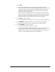
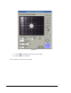
26. Use the Position Controls to align the needle tip with either the Load Cell or the
same white dot on top of the Needle Sensor, depending on your type of Needle
Sensor.
> For NSZ Series Needle Sensor, DO NOT TOUCH THE LOAD CELL with
the needle tip. Center the needle tip over the Load Cell.
> For NS Series Needle Sensor, TOUCH THE NEEDLE TIP TO THE
SUBSTRATE.
27. Click on Teach.
The dispensing head will move after your response.
> The dispensing head moves back to the Needle Sensor and automatically
locates the needle and the Height Sensor probe.
> If you get an error message that reads: “Probe to Needle Y offset (XX.XXX)
is larger than width of slots,” then adjust the Height Sensor probe so that it is
closer to the needle. Consult the Height Sensor section of the Operations
Manual for help, if necessary.
28. Place a sample substrate, or piece of paper with four dots in the shape of a square,
in the indented square on top of the Needle Sensor.
> If you have a NSZ Series Needle Sensor, there should be a simulated substrate
already present on top of the Needle Sensor.
29. Click on Next.
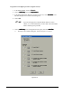
30. Select a dot style in the box below the video display.
> Consult the on-line help for assistance, if necessary.
31. Click on Next.
32. Answer “Yes” if you are asked if you want to re-teach the reference dots.
33. Use the Position Controls to center the needle tip over the first simulation dot as
shown in the on-screen prompt.
34. Click on Teach.
35. Repeat the previous 2 steps for the other three dots.
> Once you have taught the location of all four dots, FmNT automatically
dispenses the four dots, then asks for camera alignment for each dot.
36. Realign the crosshairs to the dot, if necessary, or click on click on Teach.
37. Repeat for the other three dots.
38. Click on Done to accept the results.
This concludes the tutorial on Calculate Master Offsets.