
User guide


2 Introduction
System Description
The Flow Monitoring system consists of the following components:
• Flow Meter
• Computer Interface Board
• Cable with three connectors
• Easy Coat for Windows NT/XP
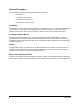
Flow Meter
The Flow Meter is a flow-sensing meter contained in a steel casing (Figure 1-1). The casing has threaded
female orifices for connections to the dispensing system fluid line. The top of the flow meter has an
electrical connector. The flow meter is mounted on a bracket at the rear of the dispensing system.
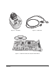
Computer Interface Board
The Computer Interface Board (Figure 1-3) is a multi-function I/O PCB card installable in a vacant
standard slot in the computer. It has a standard receptacle for the FMS Cable multi-pin I/O connector. It
includes the real time data acquisition driver LINX. The interface board is installed in the computer inside
the dispensing system.
Cables
The FMS Cable (Figure 1-2) consists of two bundled cables with one connector for the flow meter, one
connector for the 24VDC Power, and an Interface Board connector at the other end. The FMS Cable is
connected to the flow meter, computer, and power manager.
Easy Coat for Windows NT/XP
The Easy Coat software records and displays the data on a graph. If the dispensed volume is outside the
preset range, the system can be programmed to stop and sound an alarm, pause, or continue dispensing.