
Manual

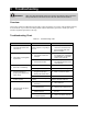


Specifications 6-3
Control
GND
V+
Emit
Rec
0
GND
D2,dir.DAC
D1,step
GND
24V
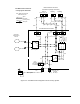
Pressure
Controller
Fiber Optic
Sensor Amplifier
GND
Control
24v
Input Air
Out Air
E/P Regulator
Supply Air, from
workcell
80-100 psi
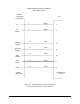
Optical Fan
Width Control
Sensors
Robot Controller Connector
Terminations (orange connectors)
Fan Width Control Enclosure
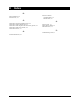
Century System Schematic
Note: Dotted line shows the
FWC Interface Unit
Brown
Blue
Blk
White
Blue
Brown
Fluid Regulator
3 way
solenoid
valve, power
off exhaust
signal
pneumatic
24 VDC (power)
fiber optic
1/4"
1/4"
1/4"
Blue BlueBlack
904
400
300
903
901
902
905
Input 3 Output 1 Output 2
24vdc 24 ret IN
-
++-
12
12
11 10 9 8
Circular Electrical Connector
Figure 6-2 Fan Width Control Integration into the Century System