
Manual


3-2 Operation
Initialization and Calibration
This section describes the steps used after initial installation, changing materials, or cleaning/replacing
components. To start this process, turn ON the dispensing system if it is not already on.
Testing Sensor and Amplifier Connections
The following steps describe how to test the FWC and make sure that it is functioning properly and
communicating with the ECNT software.
1. If ECNT is not running, start ECNT now.
2. Remove the Sensor Covers and the protective lenses from the Sensor Brackets.
3. Remove the Baffle from the Drain Pan.
4. Make sure that no obstacles are blocking the fiber optic sensors in the Sensor Fixture.
5. Make a note of the sensitivity reading on the Sensor Amplifier display.
6. In the ECNT Edit Screen, click on
Utilities.
7. Click on
Robot Utilities and select I/O Tool from the drop down menu.
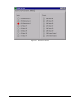
> The Robot IO Tool box opens. See Figure 3-1.
8. Click on tab
Bank C and locate the Input labeled [26] External Input-3.
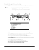
9. Slowly pass your hand between the emitter and receiver in the Sensor Fixture and check the
Input in the Robot IO Tool box to see if the light next to the Input name turns ON.
> If the Input light turns ON, the Sensor Controller is communicating properly with ECNT.
Proceed with the next step.
> If the Input light fails to respond, check the connections from the Sensor Controller to the
back panel on the dispensing system and repeat this step.
> If the Input light fails to respond after several attempts, contact Asymtek Technical
Support.
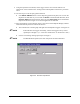
10. Click on the
X in the upper right hand corner of the Robot IO Tool box to close the box.
11. Reinstall the Baffle, the Sensor Lenses, and the Sensor Covers.
12. Once the Baffle, Sensor Lenses, and Sensor Covers have been reinstalled, check the
sensitivity reading on the Sensor Amplifier display.
> The sensitivity reading should be as close as possible to the reading taken in Step 5.
Adjust the Baffle and/or Sensor Covers to get as high of a sensitivity reading as possible.
13. Make a note of the sensitivity reading on the Sensor Amplifier display.
> This number is the “no obstruction” value, the sensitivity reading when there is nothing
between the optic sensors. You will need to compare the “no obstruction” value to
readings taken in the “Setting the Fiber Optic Fan Sensor Sensitivity” procedure below.