
Manual


2-4 Installation
Installing the Fan Width Enclosure
Tools and Materials Needed
• Phillips head screwdriver
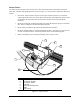
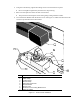
Refer to Figure 2-2 and the Specifications section of this manual for Fan Width Enclosure installation.
To install the Fan Width Enclosure:
1. Turn OFF power to the dispensing system.
2. Locate the orange connectors on the rear panel of the dispensing system and connect the
orange connectors of the Control Wire Harness as shown in the Specifications section of this
manual.
3. Find a convenient location for the Fan Width Enclosure. On top of the dispensing system or
in the lower cabinet is recommended.
4. Using the Phillips head screwdriver, remove the screws on both sides of the Fan Width
Enclosure and remove the top panel.
5. Route the fiber optic cable through the grommet on the back panel and to the Sensor
amplifier on the front panel.
?NOTE Be careful in routing and bending the optic fibers. Do not kink or bend the fibers
too sharply (greater than or equal to 2 mm).
6. Identify the transmitter (emitter) and receiver fiber cables and connect them to the appropriate
holes in the Fiber Optic Sensor Amplifier. See Figure 2-2.
> Slip the two-pronged fiber adapter over the ends of the cables.
> Lower the quick-release lever on the Sensor amplifier. Insert the adapter until the flange
on the adapter touches the amplifier.
> It may be easier to remove the amplifier from the DIN rail before inserting the fiber.
> Assemble the unit top and back panel.
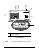
7. Connect the 16 pin circular connector end of the interface cable to the
INTERFACE connector
on the back panel of the Fan Width Enclosure (see Figure 1-3). Connect the 3-connector end
of the interface cable to the
IN3, OUT1 and OUT2 connectors on the rear panel of the
dispensing system (see Figure 2-3).
8. Connect the ¼” tube from the dispensing system fluid regulator to the
FLUID REGULATOR
PRESSURE OUT
fitting on the back panel of the Fan Width Enclosure (see Figure 1-3).
9. Connect the ¼” tube from the pneumatic port
P14 on the rear panel of the dispensing system
(see Figure 2-3) to the
SUPPLY AIR IN fitting on the back panel of the Fan Width Enclosure
(see Figure 1-3).
10. Turn ON Main power to dispensing system:
> The Pressure Controller and Fiber Optic Sensor Amplifier should turn on. If not, check
the connections to the unit or open Control Valve if pressure is not shown on the gauge.