
Manual


2-2 Installation
6. Using the 3-mm hex key, tighten the locking screws to lock each sensor in place.
> Do not overtighten. Tighten only until the screw stops turning.
7. Place one of the protective lenses in front of each sensor.
> The protective lenses keep the sensors from getting coating material on them.
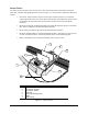
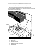
8. Cover the Sensor Brackets with the Sensor Covers. See Figure 2-1. Make sure the holes in the
covers line up with the holes in the brackets.
Item Description
1 Sensor Cable
2 Cable Clamp
3 Locking Screw
4 Sensor Clamp
5 Fiber Optic Fan Sensor
6 Sensor Bracket
7 Sensor Cover
8 Protective Lens Covering Bracket Face
9 Drain Pan Clamp
Figure 2-1 Sensor Fixture Installation
6
1
2
5
3
7
8
9
4