
Manual


1-2 Introduction
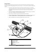
Sensor Fixture
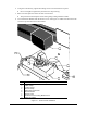
The Sensor Fixture mounts to the conveyor rail or other convenient location and includes the Sensor,
Drain Pan, and Drain Pan Mounting Plate as shown in Figure 1-1. Sensor Fixture components function as
follows:
• Fan Sensor: The Fan Sensor consists of a fiber optic emitter and receiver. The emitter
sends a light beam to the receiver that detects the intensity of the light beam. Each sensor is
clamped onto the Sensor Bracket. The Fan Sensor cables connect to the Fan Width
Enclosure.
• Drain Pan: During fan width measurement and control the dispenser sprays into the Drain
Pan, which is clamped to the Drain Pan Mounting Plate.
• Drain Tubing: The Drain Tubing drains the fluid from the Drain Pan.
• Drain Pan Mounting Plate: The Drain Pan Mounting Plate is mounted to the conveyor rail
or other convenient location. The Sensor Brackets screw into the Mounting Plate.
• Baffle: The Baffle prevents fluid from splashing onto the optic sensors.
Item Description
1 Fan Sensor (receiver)
2 Fan Sensor (emitter)
3 Fan Sensor Cables
4Drain Pan
5 Drain Pan Mounting Plate
6 Baffle
7 Drain Tubing
Figure 1-1 Sensor Fixture
5
4
2
1
3
6
7