Fan Width Control System Installation and Operations Manual The part number for this manual is 392469, Revision C. The part number for the CD version is 392468, Revision C. A cleanroom version is also available upon request. To reorder this manual, please contact Asymtek, 1-760-431-1919.
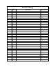
Revision History Revision Date Description Pages Affected A 7/00 Initial Release (ECO# 7191) All B 6/01 Added p/n label to back cover. None C 6/02 Updated to reflect product changes.
NOTICE All information contained in or disclosed by this document is considered proprietary by Asymtek. By accepting this material the recipient agrees that this material and the information contained therein are held in confidence and in trust and will not be used, reproduced in whole or in part, nor its contents revealed to others, except to meet the purpose for which it was delivered.
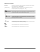
Manual Conventions Bold Text Dispensing system labels, buttons and switches, and software menu selections and commands appear in this text style. [Bracketed Text] [Bracketed Text] indicates a single key or key combination to press on a computer keyboard, such as [Enter] or [Alt + Tab]. WARNING! ? Personnel Safety Warning. This symbol appears in a shaded text block to warn you about actions that could cause personal injury or death. CAUTION! Property Damage Caution.
1 TABLE OF CONTENTS INTRODUCTION....................................................................................................1-1 Overview............................................................................................................................................ 1-1 Safety First......................................................................................................................................... 1-1 Hardware Description ...............................................
Table of Figures Figure 1-1 Sensor Fixture.................................................................................................................1-2 Figure 1-2 Fan Width Enclosure.......................................................................................................1-4 Figure 1-3 Fan Width Enclosure (Rear View)...................................................................................1-5 Figure 2-1 Sensor Fixture Installation ................................................
1 Introduction Overview This manual describes the installation, operations, and maintenance of the Fan Width Control (FWC) system. The FWC system is used with the Asymtek Century Series C-740 (conveyor) or C-741 (batch) dispensing systems. The FWC system controls the dispenser fan spray pattern using the Easy Coat for Windows NT (ECNT) software. CAUTION! Installation, operation, and service should only be performed by Asymtek-trained operators and service technicians.
Sensor Fixture The Sensor Fixture mounts to the conveyor rail or other convenient location and includes the Sensor, Drain Pan, and Drain Pan Mounting Plate as shown in Figure 1-1. Sensor Fixture components function as follows: • Fan Sensor: The Fan Sensor consists of a fiber optic emitter and receiver. The emitter sends a light beam to the receiver that detects the intensity of the light beam. Each sensor is clamped onto the Sensor Bracket. The Fan Sensor cables connect to the Fan Width Enclosure.
Fan Width Enclosure The Fan Width Enclosure is a remote enclosure that sits on top of the dispensing system or other convenient location. It is connected between the Sensor Fixture and the Robot Controller. The Fan Width Enclosure contains the electronic components for the Fan Width Control. See Figure 1-2 and Figure 1-3. The operator controls can be accessed on the front panel behind the window. Each of the components of the Fan Width Enclosure is described below.
2 1 3 4 Item 1 2 3 4 Description Pressure Controller Fiber Optic Sensor Amplifier E/P Regulator Close-up of Pressure Controller Keypad Figure 1-2 Fan Width Enclosure ? NOTE 1-4 Minor differences may exist between earlier and later configurations.
Figure 1-3 Fan Width Enclosure (Rear View) Software Description The Fan Width is controlled through the Easy Coat for Windows NT (ECNT) interface. The software is described in detail in the Easy Coat for Windows NT Help file.
2 Installation Overview If the Fan Width Control System was included as an option with the purchase of your dispensing system, most of the installation process will already be complete. The sensors and the Fan Width Enclosure will still need to be installed. This section covers the installation of the Sensor Fixture and the Fan Width Enclosure, and the setup of the ECNT Software. WARNING! CAUTION! The installation should be performed only by Asymtek-trained personnel.
6. Using the 3-mm hex key, tighten the locking screws to lock each sensor in place. > Do not overtighten. Tighten only until the screw stops turning. 7. Place one of the protective lenses in front of each sensor. > The protective lenses keep the sensors from getting coating material on them. 8. Cover the Sensor Brackets with the Sensor Covers. See Figure 2-1. Make sure the holes in the covers line up with the holes in the brackets.
9. Install the protective tubing over the sensor cables. 10. Route the fiber optic lines to the Fan Width Enclosure. 11. Use a tie-wrap to secure the fiber optic cables and tubing to the Drain Pan Mounting Plate. See Figure 2-1. 12. Using the M4 screws provided and the 2.5-mm hex key, attach the Drain Pan Clamps to the Drain Pan Mounting Plate. Do not tighten the clamps at this time. 13. Place the Drain pan in the Drain Pan Bracket. 14. Attach the Drain Tube to the outlet on the bottom of the Drain Pan. 15.
Installing the Fan Width Enclosure Tools and Materials Needed • Phillips head screwdriver Refer to Figure 2-2 and the Specifications section of this manual for Fan Width Enclosure installation. To install the Fan Width Enclosure: 1. Turn OFF power to the dispensing system. 2. Locate the orange connectors on the rear panel of the dispensing system and connect the orange connectors of the Control Wire Harness as shown in the Specifications section of this manual. 3.
4 5 1 6 2 3 Item 1 2 3 4 5 6 Description Receiver Cable Transmitter (Emitter) Cable Close-up of Amplifier Controls Fiber Optic Sensor Amplifier Adapter Quick Release Lever Figure 2-2 Fiber Optic Sensor Connection Installation 2-5
Figure 2-3 Dispensing System Rear Panel Installing the FWC Software The software is already installed when ECNT is installed on the dispensing system computer. The Fan Width Control set-up will need to be performed prior to operation and is described in the ECNT Online Help file.
3 Operation Overview WARNING! Allow only Asymtek-trained personnel to perform the following tasks. Follow the safety instructions in this document and all other related documentation. This section describes the operation of the FWC system after the initial installation on the dispensing system. ? NOTE Initialization and Calibration is an integral part of Operations.
Initialization and Calibration This section describes the steps used after initial installation, changing materials, or cleaning/replacing components. To start this process, turn ON the dispensing system if it is not already on. Testing Sensor and Amplifier Connections The following steps describe how to test the FWC and make sure that it is functioning properly and communicating with the ECNT software. 1. If ECNT is not running, start ECNT now. 2.
Figure 3-1 Robot IO Tool Box Operation 3-3
Setting the Fiber Optic Fan Sensor Sensitivity The following steps describe how to calibrate the sensitivity of the Fiber Optic Sensor Amplifier in the Windows environment. ? NOTE The Fiber Optic Sensor Amplifier settings should be as follows: Switches: D.ON Received Light Intensity: No “P” after the number on the display.
9. Using the Up-Down arrow button, set the trigger value to 90 to 100 less than the “no obstruction” value recorded in the “Testing Sensor and Amplifier Connections” procedure above. 10. The next step is to test the spray pattern detection. > If an APPLIC ON/OFF button is on the dispensing system front panel, use it to turn the dispenser ON and OFF.
Setting the Fan Width Windows Follow the ECNT Help File on setting, controlling, and measuring the fan width. Pressure Controller The Pressure Controller offers two modes of operation--Automatic and Manual. The Controller’s keypad is accessed in the Fan Width Enclosure by removing the clear front window. Software on the Controller is factory installed. When the Pressure Controller is energized, there should be information on the display if it is working properly.
Pressure Controller Function Test Perform the following test to ensure that the Pressure Controller is functioning properly. Refer to Figure 1-2 for key locations on the Controller Keypad. 1. Press F1 to enter Manual Mode. 2. Press the Up key to increase pressure in small increments. > If the pressure transducer fails to respond, check the connections between the robot and the pressure transducer. 3. Press the Down key to decrease pressure in small increments. 4.
4 Maintenance WARNING! Allow only Asymtek-trained personnel to perform the following tasks. Follow the safety instructions in this document and all other related documentation. Overview The Fan Width Control system requires Periodic Maintenance for efficient operation. Perform the following tasks as indicated. A Parts subsection is also included for ordering replacement parts. ? NOTE CAUTION! Refer to your specific dispensing system manuals for dispensing system maintenance instructions.
Parts ? NOTE Refer to the exploded view drawings below, and to Table 4-1 and Table 4-2. Fan Width Control Sensor Fixture Refer to drawing 322451 below. Fan Width Control Fan Width Enclosure Refer to drawing 338704 below.
' & % $ NOTES: 3$&.$*( 47< 6(3$5$7(/< 2) ,7(0 72 35(9(17 '$0$*( '85,1* 6+,33,1* $1' +$1'/,1* ,1',9,'8$//< 3$&.$*( 72 35(9(17 '$0$*( '85,1* 6+,33,1* $1' +$1'/,1* /$%(/ :,7+ '5$:,1* 180%(5 $1' 5(9,6,21 /(77(5 '2& 5 ( 9 $ 1 4 2 2 1 1 1 2 2 1 4 2 2 6 1 2 2 2 1 QTY.
5 Troubleshooting WARNING! Allow only Asymtek-trained personnel to perform the following tasks. Follow the safety instructions in this document and all other related documentation. Overview This section contains troubleshooting procedures. These procedures cover most of the problems that may be encountered. If you cannot solve the problem with the information given here, consult your local Nordson/Asymtek representative for help. Troubleshooting Chart Table 5-1 Troubleshooting Chart Problem 1. 2.
6 Specifications Dimensions Fan Width Enclosure Size: 40 cm (15.7 in.) wide 22 cm (8.7 in) high 22 cm (8.7 in.) deep Electrical Power: 24 VDC from the Robot Controller/dispensing system E/P Regulator: 10 VDC = 4.8 Bar (70 psi) Pneumatic Supply Air: 5.5 Bar (80 psi) minimum clean, dry air supplied through ¼” tube Drawings 1. Fan Width Enclosure Control Wire Harness: Figure 6-1. 2. Fan Width Control Integration into the Century System: Figure 6-2.
Robot Controller/Enclosure Electrical (Fan Width Control) Terminal Connector Connection 24 24 Return Direction Output Direction Output Step Output Step Output Input Pin 1 Black 2 Black 8 Blue 9 Blue 10 Blue 11 Blue 12 Blue Robot Connection 1 2 8 9 10 11 12 Interface Unit (16 pin Figure 6-1 Fan Width Enclosure Electrical Harness (Control Wire Harness part number 322453) 6-2 Specifications
Robot Controller Connector Terminations (orange connectors) Fan Width Control Enclosure Century System Schematic Input 3 24vdc 24 ret IN Note: Dotted line shows the FWC Interface Unit Output 1 + Output 2 + signal pneumatic 12 11 24 VDC (power) 1 10 9 8 2 fiber optic Blue Black Blue Circular Electrical Connector 400 904 300 901 903 Pressure Controller Optical Fan Width Control Sensors 902 Blk D2,dir.
7 Glossary ECNT: Easy Coat for Windows NT. Windows NTbased software that controls the dispenser fan spray pattern for the dispensing system. Conformal Coating System: A machine that deposits a protective coating onto components on a circuit board. Fan Width Enclosure: A remote enclosure that sits atop the dispensing system. Contains the electronic components for the Fan Width Control. Drain Pan: The mechanical portion of the FWC. Resides inside the dispensing area on the dispensing system.
8 Index –E– Pressure Controller Automatic Mode, 3-6 Manual Mode, 3-6 Electrical Harness, 6-2 Enclosure Size, 6-1 –F– Fan Width Control Fan Width Enclosure, 4-2 Fan Width Control Installation Kit, 4-2 Fan Width Control Integration into the Century System, 6-3 Fan Width Control Sensor Fixture, 4-2 Fan Width Enclosure, 1-3 –P– –S– Sensor Fixture, 1-2 Setting the Fan Width, 3-6 Software/Control, 1-5 –T– Troubleshooting Chart, 5-1 Periodic Maintenance, 4-1 Index 8-1