
Manual

5-8 Programming
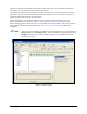
5.7 Reference Frames
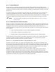
All positioning in the workcell is done with reference to sets of position coordinates, called Reference
Frames. In ECXP, three different sets of reference frames are used: Base Frame, Product Frame, and
Pattern Frame. See Figure 5-4. As you face the front of the workcell, the X-axis is left to right, the Y-axis
is front to rear, and the Z-axis is up and down. The X, Y, and Z limit switches at the front left corner of
the Base Frame define the Home or Origin position of the robot. The Z-axis is all the way up in the robot
Home position.
Product Frame
A
X
Y
B
X
Y
C
X
Y
Z Z
Z
0,0,0
A
X
Y
Z
C
X
Y
Z
B
X
Y
Z
Base Frame
Pattern
Frame
Product Length
Exploded ViewActual View
Fixture, Front
Right Constraint
Figure 5-4 Reference Frames
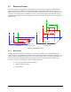
5.7.1 Base Frame
The Base Frame (See Figure 5-4, Rectangle A) is the set of coordinates (X, Y, and Z) that define the
robot's travel. The origin (Home) of the Base Frame is a known point in the workspace, defined by a set
of limit switches. In the Base Frame, the Z-axis is all the way down. When you configure the fixture, you
teach the Z-offset from the Base Frame Z by teaching Z with the nozzle touching the substrate. See
4.6 Fixture Configuration. Items that reference the Base Frame are:
• All procedures (maintenance subroutines)
• Fixture Constraint Location
• Safe Z Height