
Manual


Configuration and Characterization 4-25
4.11 Fan Width Configuration
If your system is equipped with the optional Laser Fan Width Control feature, you will need to perform a
Fan Width Setup. For additional information, refer to the manual for your Fan Width Control System or
contact your Nordson ASYMTEK representative.
To perform a fan width setup:
1. Set the air pressure for the tool whose fan width is to be configured.
a. Move the tool over the drain cup.
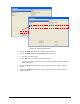
b. Select
Utilities > Pressure Adjust > Toolname from the ECXP Edit Menu.
c. Turn on the fluid and adjust the fluid pressure until you see a good, clean fan pattern.
d. Turn off the fluid and close the Pressure Adjust window by clicking on the
in the
upper right corner of the window.
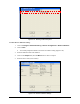
2. Select
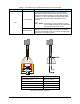
Configure > Fan Width Setup > Toolname from the ECXP Edit Screen.
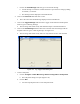
The Fan Width Control configuration window (Figure 4-25) opens.
3. Click
Find Nozzle End.
a. Click
No if the applicator is not in beam path and proceed with Step B. Otherwise, click
Yes and skip to Step C.
b. Move the nozzle into the beam.
c. Click
OK.
Applicator will move to locate nozzle tip.
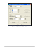
4. Click
Sensor Setup.
The applicator will momentarily spray a fan pattern through the beam to calibrate the
amplifier threshold settings for the fluid.
5. Click
Teach Width to correlate the pressure set in Step 1 with the fan width.
6. Enter the desired width in the
Width (in air) field and press the [Tab] key.
7. Click
Control Width to control the pressure until the desired fan width pattern is reached.
This pressure will override any pressure adjustment done in the Pressure Adjust
window to ensure that your pressure generates the desired width.
NOTE It is recommended to add a periodic procedure containing a Control Width or
Check Width command to the coating program to ensure consistent fan width.
The fan pattern width may change throughout the day as the temperature
changes or when using a new batch of material.