
Manual

Configuration and Characterization 4-15
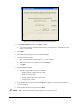
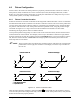
6. Teach the coordinates as described below. See Figure 4-17 for coordinate locations. This
example is for a front-right constraint, which is the normal setting for a left-to-right
conveyorized system.
a. Move the robot until the camera crosshairs are directly over the constrained board
corner.
b. Click
Teach X to teach the X-coordinate and click Teach Y to teach the Y-coordinate.
7. Click
Close to exit fixture configuration.
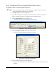
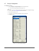
8. In the Edit Screen, select the fluid dispensing applicator as the tool (Figure 4-16).
Be sure to use the applicator with the smallest coating height.
Figure 4-16 Active Tool – Select Coat 5-Axis
9. Install the nozzle on the fluid dispensing applicator. The nozzle must be installed in order to
accurately teach the Z-coordinate.
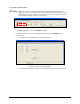
10. Click on
Configure > Fixtures from the ECXP Edit Screen.
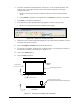
11. To teach the Z-coordinate, carefully lower the nozzle until it is just touching the surface of
the board (Z-coordinate on the Front View - Figure 4-17).
12. Click on the
Teach Z button.
13. Click on
Close when done.
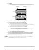
Z
Front View
Y
Top View
Z
X
Y
X
Board
Stop
Use this edge to “Teach X”
Use this surface to “Teach Z”
Use the applicator with th e smallest coating height
Use this edge to “Teach Y”
Board Travel
Figure 4-17 Teaching "Front Right" XYZ Coordinates