
Manual


4-6 Configuration and Characterization
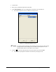
9. Move the Z-head to its upper limit and position the camera cross-hairs/laser pointer over the
mark in the dilatant compound.
10. Click
OK.
Offsets for the tool have been taught relative to the camera/laser pointer.
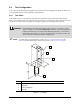
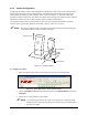
Since the tool tip is usually in front of and below the tooling pin, the Y and Z offsets are
typically negative. Positive X is to the right of the tooling pin as shown in Figure 4-1.
11. Repeat the above procedure for each tool.
NOTE If the offsets for the tool or camera are potentially changed (e.g. when the needle is
replaced and no needle sensor is present, if the camera is removed or replaced, if the tool
setup changes) tool offsets should be redefined.
4.4.1.1 Dual Applicators/Needle Finder
This feature supports the needle finder option, but it is useful for other dual-applicator systems as well.
With dual-applicators, it is used to set the offset of one applicator using another as a reference.
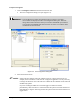
To define tool offsets for dual applicators:
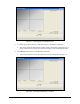
1. Click on the
Teach Relative button and follow the prompts.
2. Choose a reference tool from the drop-down menu in the Tool property.
3. Move that tool to a reference point.
4. Move the second tool to the reference point.
ECXP then calculates the required offset for the second tool and sets it.
This feature is useful for any dual-applicator system, and is present whether or not a needle finder is
configured.
4.4.1.2 Laser Pointer
The Z-offset for the optional Laser Pointer should be the same as the installed applicator. The offsets for
the applicator and Laser Pointer are normally set at the factory before a system is shipped, but should be
checked during system configuration.
The Laser Pointer Z-offset is relative to the tooling pin. When the Z-head is at the upper Z-limit, the spot
generated on the board by the Laser Pointer represents the tool tip. Therefore, the offset is always
-200.8 mm (-7.916 in.).