
User Manual

Configuration and Characterization 4-15
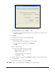
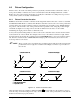
6. Teach the coordinates as described below. See Figure 4-17 for coordinate locations. This
example is for a front-right constraint, which is the normal setting for a left-to-right
conveyorized system.
a. Move the robot until the camera crosshairs are directly over the constrained board
corner.
b. Click
Teach X to teach the X-coordinate and click Teach Y to teach the Y-coordinate.
7. Click
Close to exit fixture configuration.
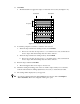
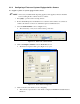
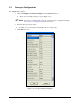
8. In the Edit Screen, select the fluid dispensing applicator as the tool (Figure 4-16).
Be sure to use the applicator with the smallest coating height.
Figure 4-16 Active Tool – Select Coat 5-Axis
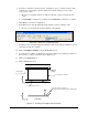
9. Install the nozzle on the fluid dispensing applicator. The nozzle must be installed in order to
accurately teach the Z-coordinate.
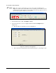
10. Click on
Configure > Fixtures from the ECXP Edit Screen.
11. To teach the Z-coordinate, carefully lower the nozzle until it is just touching the surface of
the board (Z-coordinate on the Front View - Figure 4-17).
12. Click on the
Teach Z button.
13. Click on
Close when done.
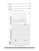
Z
Front View
Y
Top View
Z
X
Y
X
Board
Stop
Use this edge to “Teach X”
Use this surface to “Teach Z”
Use the applicator with the smallest coating height
Use this edge to “Teach Y”
Board Travel
Figure 4-17 Teaching "Front Right" XYZ Coordinates