
User guide

4-6 Configuration and Characterization
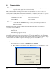
10. Position the tool tip over the left intersection of the dotted lines and click Next.
11. Position the tool over the right intersection of the dotted lines and click
Next.
12. Position the tool tip over the right dotted line and the back line and click
Next.
! Remove any teaching devices before continuing.
13. Click
Next.
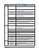
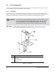
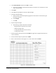
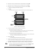
! The Wizard will now apply three stripes of material to the test area (See
Figure 4-5).
Desired Start Desired End
2
nd
3 passes
Stripe with Best
Ending Accuracy
Stripe with
Best Starting
Accuracy
1
st
3 passes
Desired Start Desired End
2
nd
3 passes
Stripe with Best
Ending Accuracy
Stripe with
Best Starting
Accuracy
1
st
3 passes
Figure 4-5 Material Characterization
14. You will be prompted to teach the coordinates of the test area.
a. Teach the stripe with the best starting accuracy.
! If none are exact but one stripe starts too soon and the next too late, teach between
the two stripes. The Wizard interpolates the values of the two.
b. Teach the stripe with the best ending accuracy.
! If none are exact but one stripe ends too soon and the next too late, teach between the
two stripes. The Wizard interpolates the values of the two.
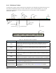
15. Enter the stripe width.
! The Wizard applies three more stripes to the test area.
16. Check the starting and ending points of the second three stripes. If they are not accurate,
rerun the characterization, making adjustments as necessary to obtain the best results.
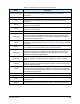
17. The settings will be displayed for your approval. The only variable you can change is the
stripe width. To change any other settings, you will have to rerun the characterization.
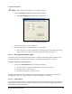
TIP To perform a characterization from the ECXP Edit screen, click on Configure > Tools.
The Tool Configuration dialog box opens. Select the tab for the tool you wish
characterize, then click the
Configure button.