
User guide

Configuration and Characterization 4-3
To define Tool Offsets:
" NOTE Before defining tool offsets, see the warning on Page 4-2
1. Click on
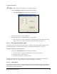
Configure > Tools from the Edit Screen menu bar.
! The
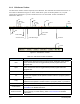
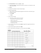
Tool Configuration dialog box opens. See Figure 4-2.
Figure 4-2 Tool Configuration Dialog Box
2. Select the tab for the tool to be configured.
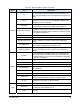
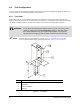
3. Enter the appropriate Tool Offsets for the X, Y, and Z fields.
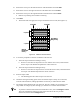
! Since the tool tip is in front of and below the tooling pin, the Y and Z offsets are always
negative. Positive X is to the right of the tooling pin, as shown in
Figure 4-1.
4.4.1.1 Dual Applicators/Needle Finder
This feature supports the needle finder option, but it is useful for other dual-applicator systems as well.
With dual-applicators, it is used to set the offset of one applicator using another as a reference.
To define tool offsets for dual applicators:
1. Click on the
Teach Relative button and follow the prompts:
a. Choose a reference tool from the drop-down menu in the Tool property.
b. Move that tool to a reference point.
c. Move the second tool to the reference point.
ECXP then calculates the required offset for the second tool and sets it. This feature is useful for any
dual-applicator system, so is present whether or not the needle finder is configured.
4.4.1.2 Laser Pointer
The Z-offset for the optional Laser Pointer should be the same as the installed applicator. The offsets for
the applicator and laser pointer are normally set at the factory before a system is shipped, but should be
checked during system configuration.