
Manual

Configuration and Characterization 4-17
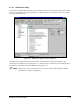
4.7.5.1 FWC Sensor Setup
As part of the Fan Width Setup procedure, you will need to perform a FWC Sensor Setup. ECNT contains
a macro to automate this procedure. See Figure 4-13. Refer to the Laser Fan Width Control Users Guide
for step-by-step instructions.
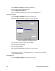
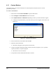
Figure 4-13 FWC Sensor Setup Procedure in Macro1
The FWC sensor setup procedure in Macro1.ECM is used to set the trip point of the amplifier. The
routine moves the applicator to an appropriate X, Y, and Z position over the drain pan. The fluid stream is
then turned on in the laser path and the differential trip point is set.
" NOTE Refer to the Laser Fan Width Control Users Guide or ECNT Online Help for detailed
information on software configuration.