
Manual

4-16 Configuration and Characterization
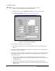
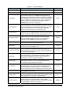
Table 4-3 Fan Width Control Configuration Window Options (Continued)
Category Item Description
Control Width
Pressing this button will first run the Locate Nozzle End
instruction and update the XYZ nozzle position. After the
nozzle is successfully located, the Control Width algorithm
will start to run. The Control Width will automatically adjust
the fluid pressure until the target width (Width In Air) is
achieved.
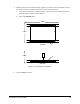
" NOTE After teaching a new target width, running
Control Width will update the offsets between
the fan pattern and nozzle centers.
Test
Measure Width
Measures the width corresponding to the current fluid system
settings and records the value in the Width (In Air) display
box. This value will then be the new Target Fan Width used in
subsequent control width routines.
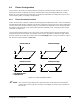
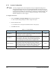
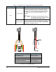
Description Default Values
Target Width (T.W.) .50 in. (12.7 mm)
Width Warning Tolerance (W.T.) .015 in. (.38 mm)
Width Error Tolerance (E.T.) .030 in. (.76 mm)
Offset Warning Tolerance .015 in. (.38 mm)
Offset Error Tolerance .030 in. (.76 mm)
Figure 4-12 Fan Width Tolerance