
Manual

Configuration and Characterization 4-15
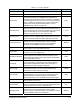
Table 4-3 Fan Width Control Configuration Window Options
Category Item Description
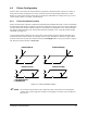
Sensor Fixture Rotation
Use 0 degrees for beam parallel to Y-axis, 90 degrees for
beam parallel to X-axis.
XYZ Values
Displays the X, Y, and Z coordinate captured during the Find
Nozzle End routine. These values CANNOT be typed in
manually.
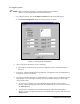
Sensor Setup
Establishes the threshold of the amplifier that is used for
detecting the edge of the fan pattern. This button runs the
FWC Sensor Setup Macro in the Macro1.ecm file. The factory
default routine will move center of the applicator tip to 0.30
inches above the laser beam and turns the fluid stream on.
Find Nozzle End
Establishes the position that the fan width control functions
are performed. Software prompts user to move applicator tip
over drain pan, then automatically determines the center of
the barrel and records the X, Y, and Z coordinates.
Locate Gun Barrel
Rotate
This value must be typed in manually the first time. The value
can be 0, 90, 180, or 270 degrees. This is the position that
the applicator will rotate so that the fan pattern is
perpendicular to the laser beam.
Width (In Air)
The target fan width used for the production process. This
value is used during control width routine and it is used to
calculate the offset and warning tolerances. If the desired
width in air is know, it can be typed in manually, but a Control
Width must then be performed to update the offsets.
Height
(for Reference)
Displays the height the nozzle tip is positioned above the
beam to perform the Measure, Teach, and Control Width
functions. This value is cannot be typed in manually. This
value is the height established in the tool characterization
process.
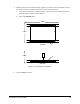
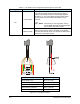
Width Warning
Tolerance
(See Figure 4-12)
Overall Fan Width (In Air) ± 0.015” (0.38mm) by default.
Example: If the target Fan Width is 0.500” and the measure
width is greater than 0.515” or less than 0.485”, a yellow
warning message is logged in the Production Event Monitor.
Width Error
Tolerance
(See Figure 4-12)
Overall Fan Width (In Air) ± 0.030” (0.76 mm) by default.
Example: If the target Fan Width is 0.500 inches and the
measure width is greater than 0.530” or less than 0.470”, the
program will stop or run a user-defined error procedure. A red
error message is logged in the Production Event Monitor.
Offset Warning
Tolerance
(See Figure 4-12)
Difference between the center of the Fan Pattern and the
center of the nozzle tip. Default value is .015” (0.38 mm). If
exceeded, a yellow warning message is logged in the
Production Event Monitor.
Offset Error
Tolerance
(See Figure 4-12)
Difference between the center of the Fan Pattern and the
center of the nozzle tip. Default value is .030” (0.76 mm). If
exceeded, a red warning message is logged in the Production
Event Monitor.
Teach Width
Teach Width
Button
Measures the width corresponding to the current fluid system
settings and records the value in the Width (In Air) display
box. This value will then be the new Target Fan Width used in
subsequent control width routines.