
Manual

Configuration and Characterization 4-3
To define Tool Offsets:
WARNING! If Tool Offsets have already been defined and set up in the Tool Library, correct
offsets are displayed in the Tool Configuration dialog box. DO NOT change
them without assistance from your Asymtek representative. Your Asymtek
representative can supply you with the offset coordinates for each tool used.
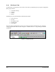
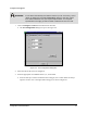
1. Click on Configure > Tools from the Edit Screen menu bar.
! The
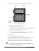
Tool Configuration dialog box opens. See Figure 4-2.
Figure 4-2 Tool Configuration Dialog Box
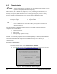
2. Select the tab for the tool to be configured.
3. Enter the appropriate Tool Offsets for the X, Y, and Z fields.
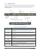
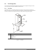
! Since the tool tip is in front of and below the tooling pin, the Y and Z offsets are always
negative. Positive X is to the right of the tooling pin, as shown in Figure 4-1.