
Installation Owner's manual


Install the
Dispensing
Valve
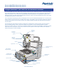
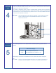
Prior to installing the Dispensing Valve, loosen (do not remove) the four (4) screws on the
Z-axis face plate and slide the face plate up so that it is flush with the Z-axis extrusion.
Tighten the screws on the face plate.
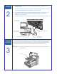
To install the Dispensing Valve, slide the dovetail bracket (included with the Dispensing
Valve) into the Valve Mounting Bracket on the Z-axis face plate. Secure by tightening the
quick release lever on the Valve Mounting Bracket. Refer to the DispenseMate 580 Series
User Guide for additional information.
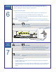
"NOTE After the Dispensing Valve has been installed, you must adjust the Height
Sensor Probe. Refer to the DispenseMate 580 Series User Guide for
additional information.
4
Electrical
Connections
5
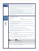
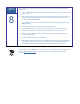
Electrical Requirements for the DispenseMate 583/585 Dispensing Systems are as
follows:
Main Power Supply
D-583
D-585
1 kw of single-phase power at
100/120/220/240 VAC; 50/60 Hz; 10 A
Board wiring connections are installed in the factory before the product is shipped.
"NOTE Refer to of the DispenseMate 580 Series User Guide for information on
available electrical diagrams or contact your Asymtek Representative.
Z-Axis Face Plate
Quick Release Lever
(raise up to tighten)