
Installation Manual

Asymtek Headquarters
2762 Loker Avenue West
Carlsbad, CA 92010-6603 USA
Tel: (760) 431-1919
1-800-ASYMTEK (1-800-279-6835)
P/N 7203951, Revision B ©2005
Connecting
the Power
and Air
Supply
6
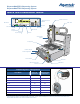
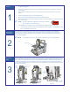
1. Unpack the Main Power cable and remove all packing material including plastic wrappers and
tie wraps.
2. Plug the female end of the power cable into the Main Power Inlet on the back of the dispensing
system. Plug the male end of the power cable into the facility power source.
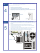
3. Attach a quick disconnect air fitting (customer supplied) to the facility air hose.
4. Connect the facility air hose to the Main Air Pressure Regulator Inlet.
5. Connect the outlet of the Main Air Pressure Regulator to the Main Air Inlet on the rear of the
dispensing system.
" NOTE The maximum air supply pressure should not exceed 100 psi (689 kPa).
System
Power-up
7
1. Turn the Main Power Switch on the back of the system to the ON (I) position.
2. Turn the Computer power switch to the
ON (I) position.
! The system Computer should begin the boot up sequence.
3. Check the EMO button to see if it has been activated. If it has been activated, deactivate it by
turning the red knob clockwise until the knob pops out.
4. Make sure the interlock signal is not interrupted. Close the dispensing system front doors if
applicable.
5. Press
Start on the Control Panel.
! The dispensing system should be in a powered-up state and the digital gauges should be on.
If not, make sure the power cord is properly connected to the dispensing system and to an
active facility power source.
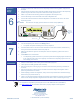
Helpful Hints
• Always consider safety when working around automated equipment.
• Wear gloves and safety glasses when necessary.
• Disconnect and place a warning tag on the Main Power Inlet before performing maintenance
or service.
• Disconnect and place a warning tag on the Main Air Pressure Gauge and Regulator before
performing maintenance or service.
• When adjusting pressure with regulators, always reduce the pressure below the desired range
before turning the pressure back up.
• There is an important correlation between the position of the Dispensing Valve tip and the Height
Sensor Probe. Always adjust the Height Sensor Probe after a valve or needle length change.
This equipment is regulated by the European Union under WEEE Directive (2002/96/EC).
See www.nordson.com
for information about how to properly dispose of this equipment.
Main Power Inlet
Main Air Inlet
Main Air
Pressure
Regulator
Inlet