
Installation Manual

Adjusting the
Height Sensor
Probe
4
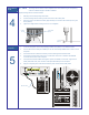
" NOTE The Height Sensor Probe must be adjusted each time a different type of Dispensing
Valve or a different length of needle is installed.
Adjust the Height Sensor Probe as follows:
1. Manually move the Dispensing Head down.
2. Loosen the Height Sensor locking screw at the back of the Z-axis plate.
3. Move the probe to the desired location (approximately 10 mm below the needle tip in the gear
down position).
4. Tighten the Height Sensor locking screw. Do not overtighten.
10 mm
(0.394 in.)
Installing the
Computer
5
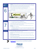
1. Locate the Computer, remove all packaging material, and place it in the desired location.
2. Connect the RS-232 cable (P/N 7200897) to the rear of the DispenseMate and to COM 1 on the
Computer.
3. Connect the Monitor cable to the Monitor port and hand-tighten the thumbscrews.
4. Connect the keyboard and mouse to the Y-Cable and connect the Y-Cable to the MSE/KB
connection at the back of the Computer.
5. If the optional Automatic Pattern Recognition System is installed, connect the “Light Source”
Cable (P/N 06-2215-01) and “Camera” Cable (P/N 06-0078-00) to the Computer.
6. Plug the Computer power cable and the Monitor power cable into the facility outlet.
RS-232 Cable
Locking
Screw
Z-Axis Plate
(Back)