
Installation Manual

Uncrating and
Placing
1
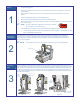
1. Locate and remove the envelope on the outside of the shipping crate. Open the envelope and
locate the shipping list.
2. Cut the four bands that secure the lid to the crate. Remove the lid, four cardboard corners and
plastic sleeve.
3. Remove the poly bag from the unit and cut the bands that secure the dispenser to the crate
bottom.
4. Place the dispensing system near the installation site.
5. Remove all perimeter packaging material from the dispensing area.
6. Remove all tie wraps, tape, foam packaging material, and warning tags from the Dispensing Head
and Tooling Plate.
" NOTE Location of packaging materials to be removed is indicated
by the presence of red warning tags.
7. Use the flat bar and hammer to remove the crate lid and unpack the accessories crate.
! As you unpack each item inside of the box, identify the item, locate it on the shipping list, and
place a checkmark next to the item.
Installing and
Leveling the
Tooling Plate
2
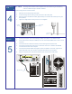
DispenseMate Series 550 Dispensing Systems are supplied with tooling plates that are adjusted to
±127mm of the X-Y dispense level plane. The tooling is removed from the system prior to shipping to
prevent damage and must be reattached during installation. Attach the tooling plate using the four (4)
m4 x 0.7 screws supplied.
" NOTE The leveling set screws are preset at the factory and should not need adjustment.
Installing the
Dispensing
Valve
3
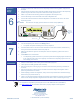
Prior to installing the Dispensing Valve, loosen the six (6) screws on the Z-axis face plate (Figure A) and
slide the face plate up so that it is flush with the Z-axis extrusion (Figure B). Tighten the screws on the face
plate. To install the Dispensing Valve, slide the dovetail bracket (included with the Dispensing Valve) into
the Valve Mounting Bracket on the Z-axis face plate. Secure by tightening the socket head cap screw on
the Valve Mounting Bracket (Figure C). Refer to the manual applicable to your particular Dispensing Valve
for additional information.
Tooling Plate
Z-Axis
Extrusion
Z-Axis
Face
Plate
Figure B Figure A Figure C
Valve
Mounting
Bracket
Socket Head
Cap Screw